Getting Started
Features and Operations Overview
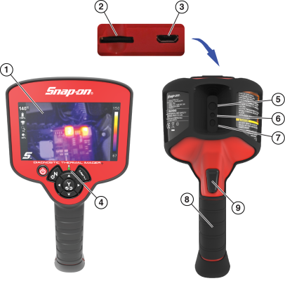
| 1. | Display |
| 2. | microSD (Secure Digital) Card |
| 3. | micro USB Jack |
| 4. | Battery Charging LED |
| 5. | Thermal Window |
| 6. | Visual Light Window |
| 7. | LED Spotlight |
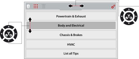
Use the Control Buttons to navigate the menus and toolbar.
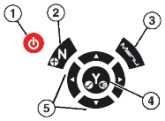
| 1. | Power Button On / Off |
| 2. | No / Cancel & Enable / Disable video recoding |
| 3. | Menu Button |
| 4. | Yes / Accept & LED Spotlight On / Off |
| 5. | Directional Control (Left/Right - View Setting Selection) (Up/Down - Overlay Setting Selection) |
Press the Menu button to open the Menu screen.
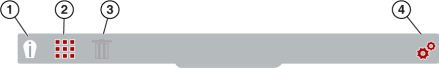
| 1. | Expert Tips |
| 2. | Image Gallery |
| 3. | Delete Image |
| 4. | Settings |
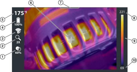
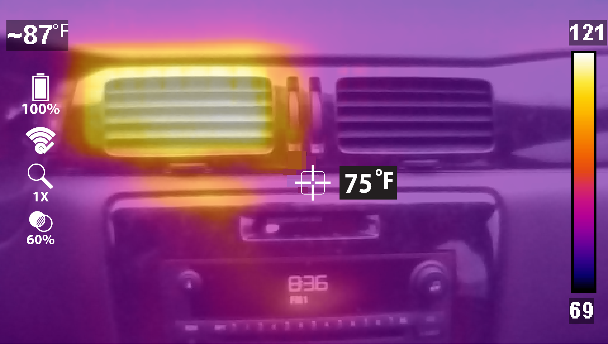
| 1. | Opacity Percentage Icon |
| 2. | Zoom Level Icon |
| 3. | Wi-Fi Icon |
| 4. | Battery Level Icon |
| 5. | Center Region Temperature (Average) |
| 6. | Target (Center Region Temperature (Average)) |
| 7. | Menu Indicator Tab |
| 8. | Color Palette-Maximum Temperature Value |
| 9. | Color Palette Range Indicator |
| 10. | Color Palette-Minimum Temperature Value |
|
Use
|
|||
|---|---|---|---|
|
1X Zoom |
|||
|
|
Displays at 1X zoom in center of screen
|
||
|
2X Zoom |
|||
|
|
Displays at 2X zoom full screen
|
||
|
Picture in Picture |
|||
|
|
Center section of image displays at 100% opacity over visual light image
|
||
|
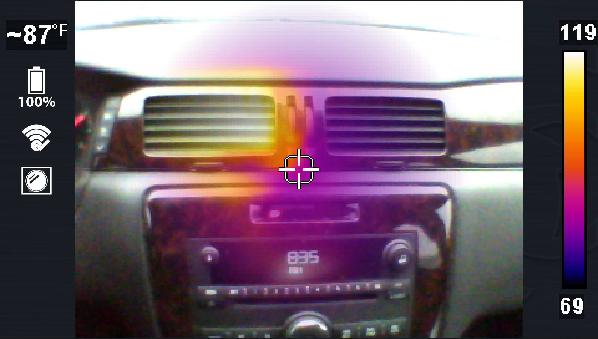
Diffused Beam |
|||
|
|
Displays at 100% opacity at the center and gradually decreases radially to 0%.
|
||
|
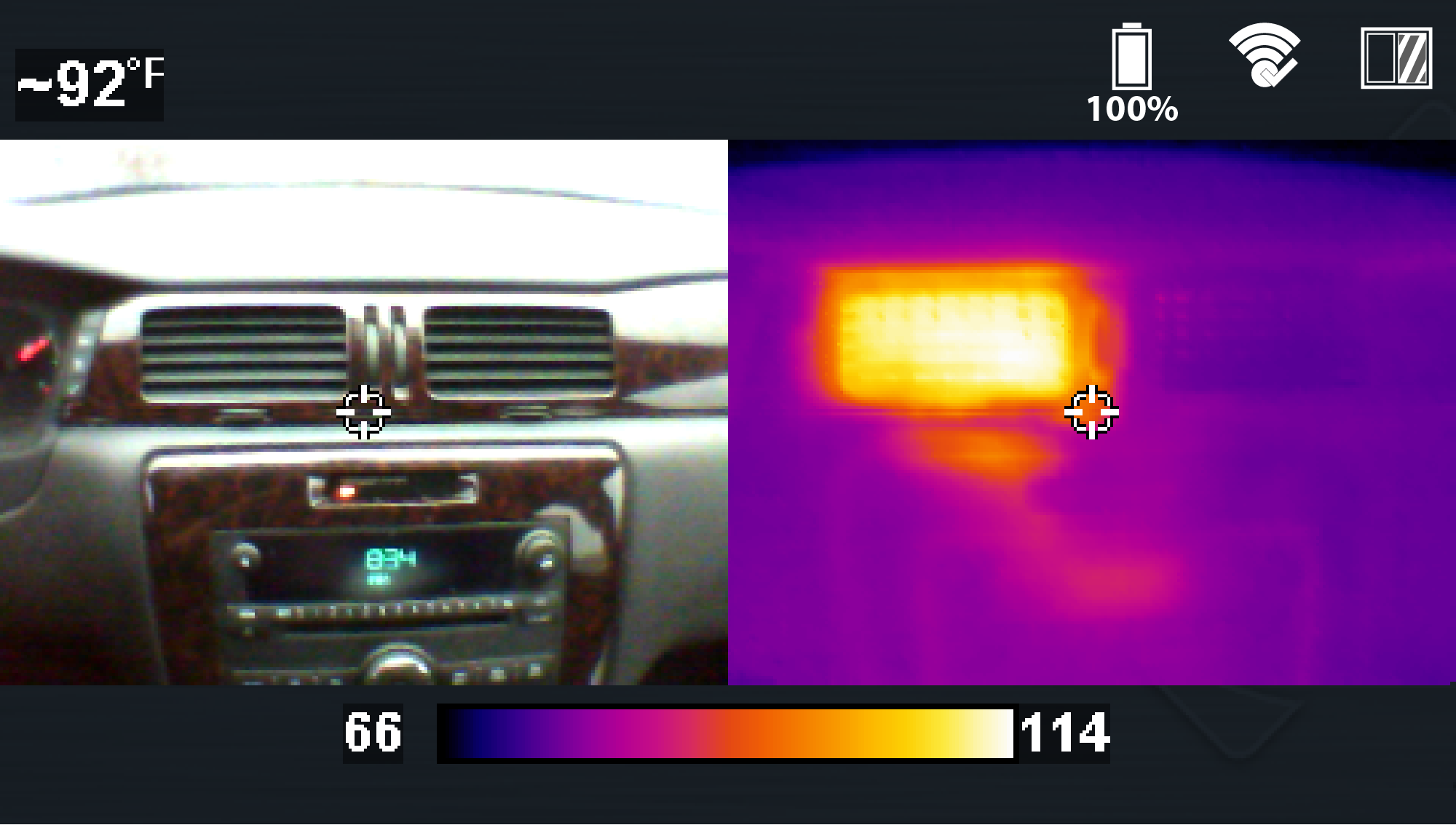
Split Screen |
|||
|
|
Side-by-side images, Right side displays at 100% opacity, Left side displays visual light image
|
||

Thermal opacity can only be changed in 1X and 2X Zoom Modes.
There are six settings, 0% Visual Light, 20%. 40%. 60%, 80% and 100% Full Thermal. Examples shown below.
|
Use
|
|||
|---|---|---|---|
|
0% Thermal Opacity (Visual Light) |
|||
|
|
Displays objects at 0% overlay opacity, similar to a standard visible light digital camera. |
||
|
60% Thermal Opacity |
|||
|
|
Displays with 60% overlay opacity |
||
|
100% Thermal Opacity (Full Thermal) |
|||
|
|
Full Thermal Mode displays objects with 100% overlay opacity |
||

This setting is only available in 2X zoom display mode.
Using Freeze Image gives you the ability to add temperature markers (up to five) to a captured image.
Tips:
| ● | Activating the trigger after anchoring a marker, saves the image. |
| ● | With atleast one marker set you can save the image by activating the trigger, or you can continue to add more markers (up to five) and then activate the trigger to save the image with all the markers. |
| ● | After activating the trigger and saving an image, you can clear the markers and reuse the same image to position new markers, by pressing Menu then the "N" button. This refreshes the image, allowing you to start again and place new markers. Activate the trigger when done to save the image. |
Adding Markers / Saving an Image with Markers
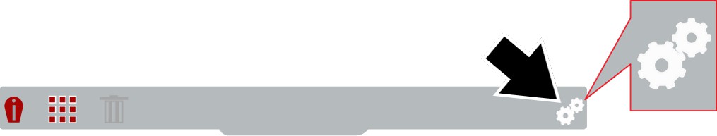
| 1. | Press the Menu button, then from the toolbar select the Settings  icon. icon. |
| 2. | From the Settings menu, select "Trigger Button Function" and then select "Freeze Image" |
| 3. | Return to Live Mode and select the 2X zoom display mode. (Use   to toggle though the modes) to toggle though the modes) |
| 4. | Aim the imager and activate the trigger. Activating the trigger displays a still image on the screen and a screen message pops up "Press "Y" key to add freeze marker". |
| – | If you want to add a marker at the default center position, press the "Y" key, or.. |
| – | If you want to add a marker at a different position, use to move the marker. |
| 5. | Press the "Y" key to anchor the marker in place. |
An anchored marker is indicated by the white background temperature indicator.
| 6. | To add another marker (up to five) use |
| 7. | Again, press the "Y" key to anchor the marker in place. |

| 8. | Repeat to place up to five markers. |
| 9. | Activate the trigger after anchoring any marker, to save the image. |
1. Press Menu , then select Settings from the toolbar.
2. Select Language and then select the desired language.
Router and network must be configured for 2.4GHz (5GHz is not supported). Ensure you are using either (WPA/WPA2 - Personal ) or (WPA/WPA2 - Enterprise for Client) Security Standards.
| 1. | Turn on the thermal imager and press the Menu button. |
| 2. | Select Settings from the toolbar, then select Wi-Fi Connection. |
| 3. | To turn Wi-Fi on, press the UP button to select the Wi-Fi Power icon, then press the Y button to turn Wi-Fi on. |
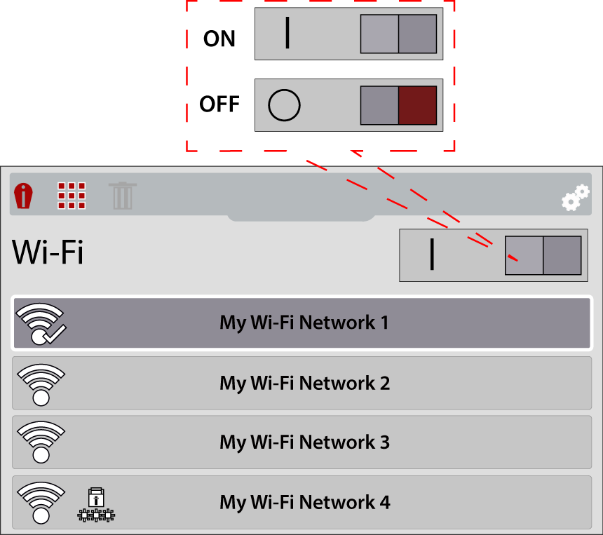
| 4. | Press the Down button to enter the Wi-Fi network list, then use the Up / Down buttons to select a wireless network. Press the Y button to enable the selection. |
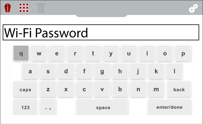
| 5. | If a password is required when choosing a secured (protected)  network, enter the password using the on-screen keyboard and the directional control buttons. Select the “enter/ done” key when finished. network, enter the password using the on-screen keyboard and the directional control buttons. Select the “enter/ done” key when finished. |
When successfully connected to a Wi-Fi network, a check mark will display on the Wi-Fi icon.
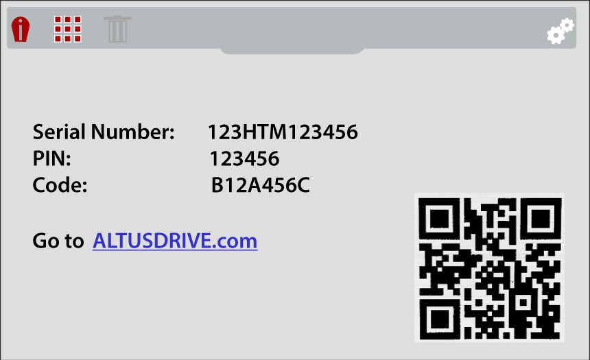
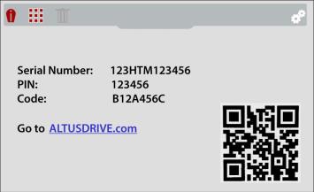
| 6. | A confirmation screen displays showing the device serial number, PIN and Code. These numbers are needed for your Snap-on Technician Profile setup. |
Use the QR code to open ALTUSDRIVE.com on your mobile device.
If you are a new owner of this tool, you must add this device to your Technician Profile in order to transfer files to your Snap-on Cloud account. If you do not add the device to your profile, captured files will be sent to the previous owners account.
|
Wi-Fi - ON / Connected to network access point and Internet |
|
Wi-Fi - ON / Alternate available network access point |
|
|---|---|---|---|
|
Wi-Fi - ON / Not connected to network access point or Internet |
|
Wi-Fi - ON / Network access point password protected |
|
|
Wi-Fi - ON / Connected to network, not connected to Internet |
|
Wi-Fi - ON / Actively connecting to network access point |
|
|
Wi-Fi - OFF |
|
Wi-Fi - ON / Actively disconnecting from network access point |
|
|
Wi-Fi Signal Strength (general): Three bars - Full Strength Signal Zero bars - Weak Signal |
|
||


Rrouter and network must be configured for 2.4GHz (5GHz is not supported). Ensure you are using either (WPA/WPA2 - Personal ) or (WPA/WPA2 - Enterprise for Client) Security Standards.
Mobile device hot spot connection guidelines:
iOS (Typical)
| 1. | Click on “Settings”  |
| 2. | Click on “Personal Hotspot”  |
| 3. | Turn ON “Maximize Compatibility” 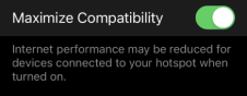 |
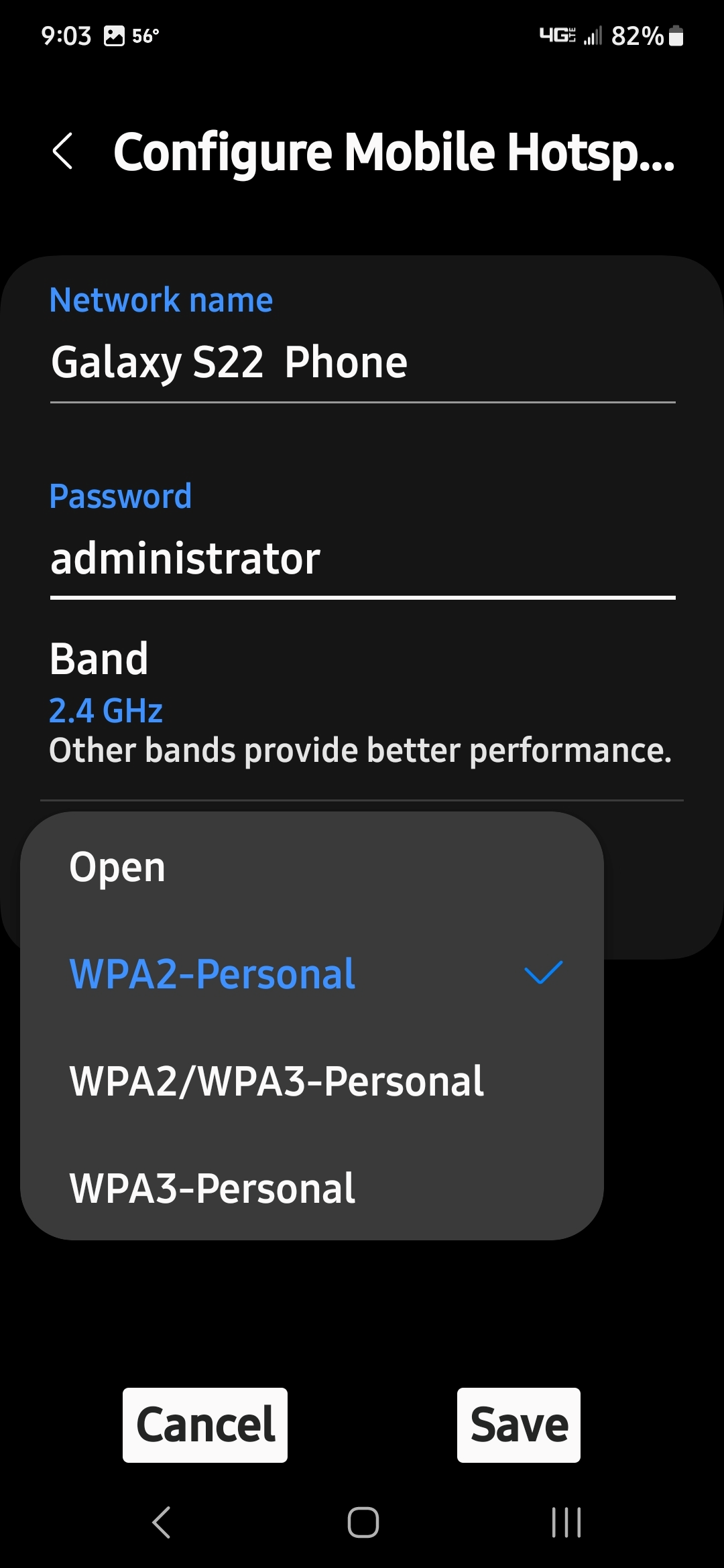
Android (Typical)
| 1. | Click on “Wi-Fi Settings” |
| 2. | Click on “Configure Mobile Hotspot” |
| 3. | Select “WPA2-Personal” |
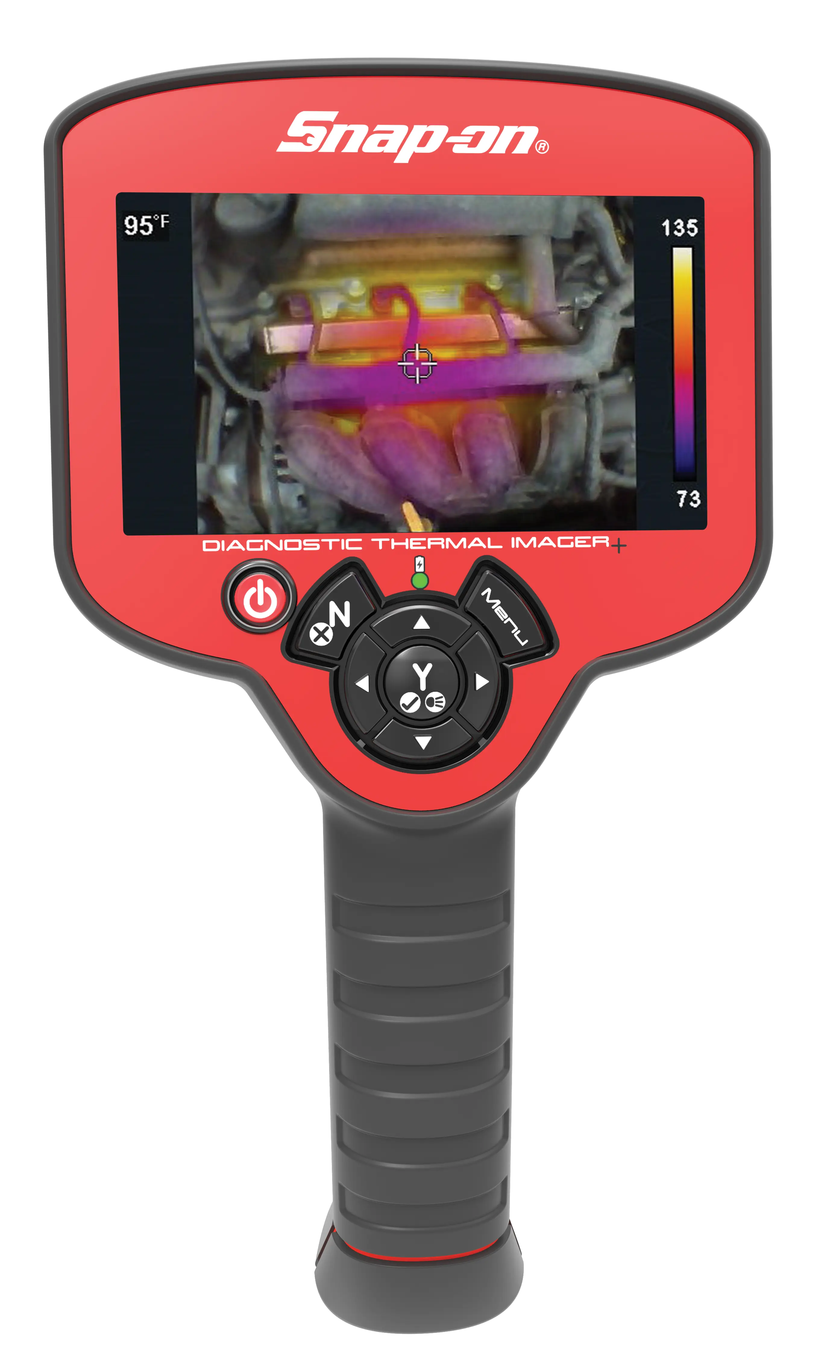
After startup the Thermal Imager+ is in live capture mode. This allows you to make thermal measurements and capture still images and videos.
| – | To ensure optimal measurement accuracy, it is recommended to allow the Thermal Imager to “warm-up” a minimum of 5 minutes before taking measurements. |
| – | The temperature readout is not displayed for approximately 30 seconds upon startup. This is normal due to the unit automatically calibrating upon startup. |
| – | Opacity and view settings are saved when the thermal imager is turned off, allowing you to resume operation with the same setting you last used. |
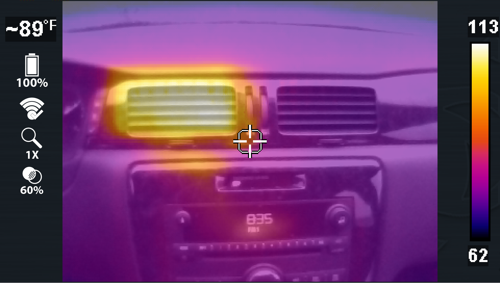
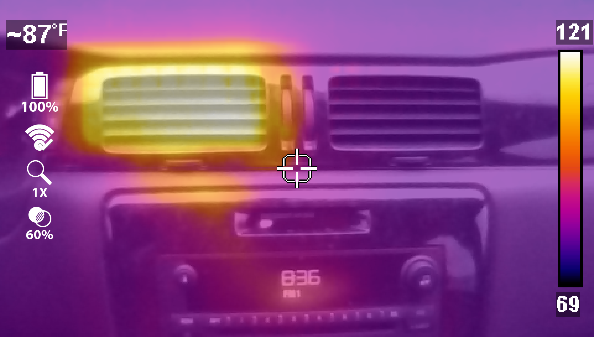
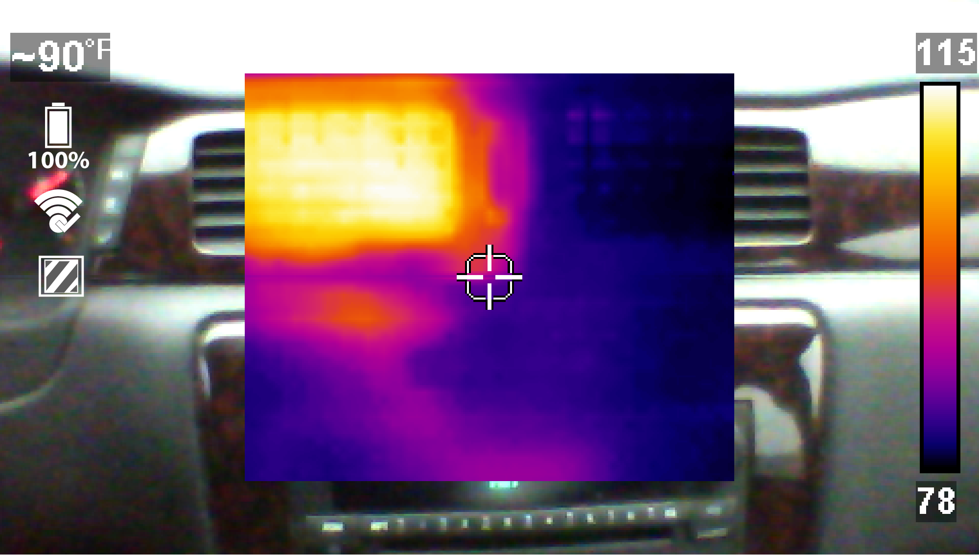
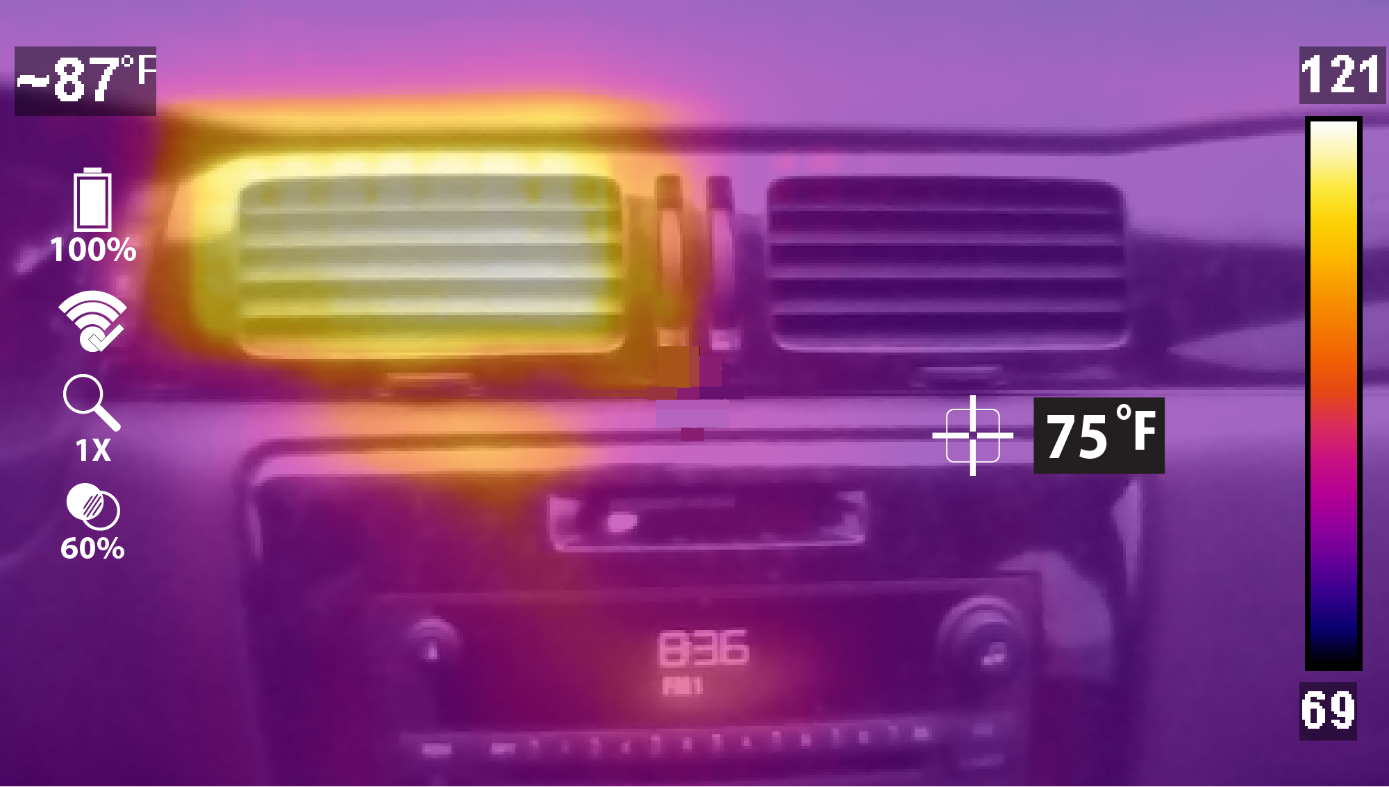
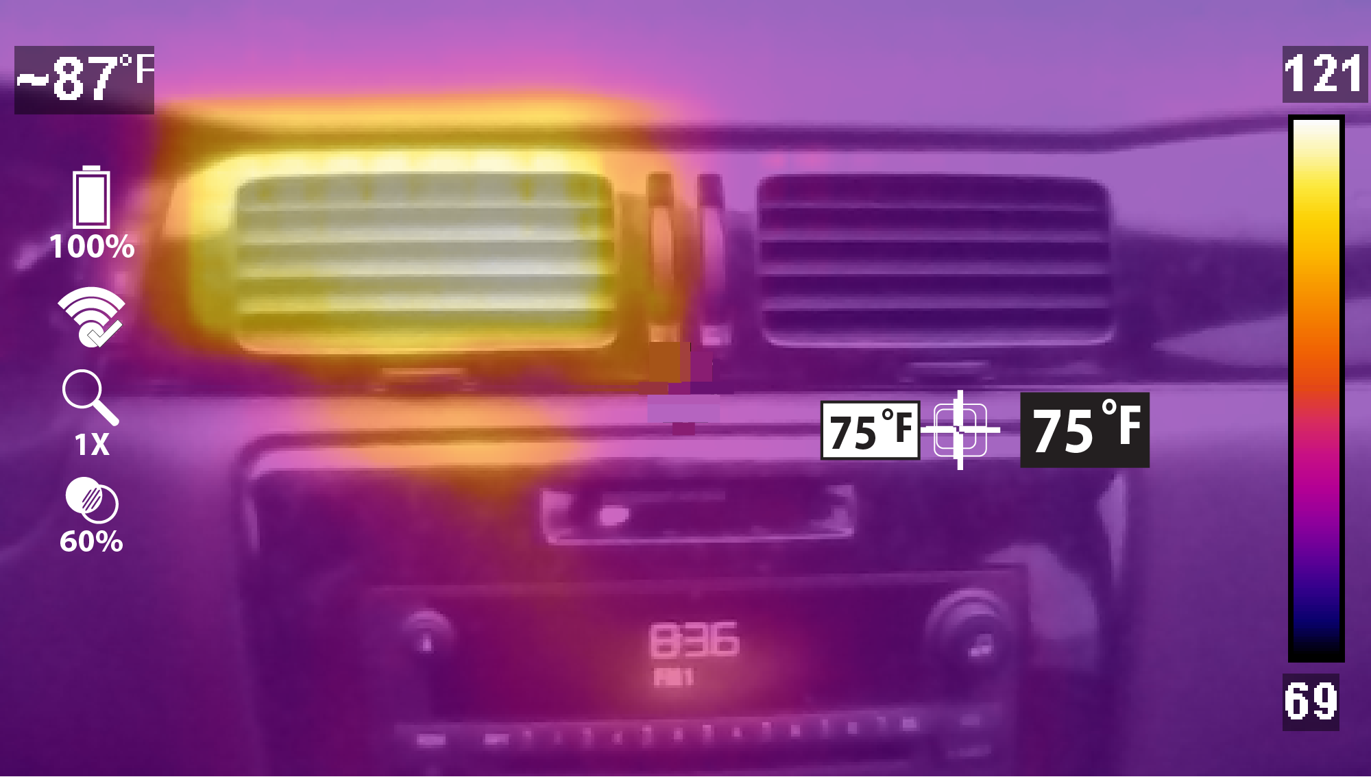
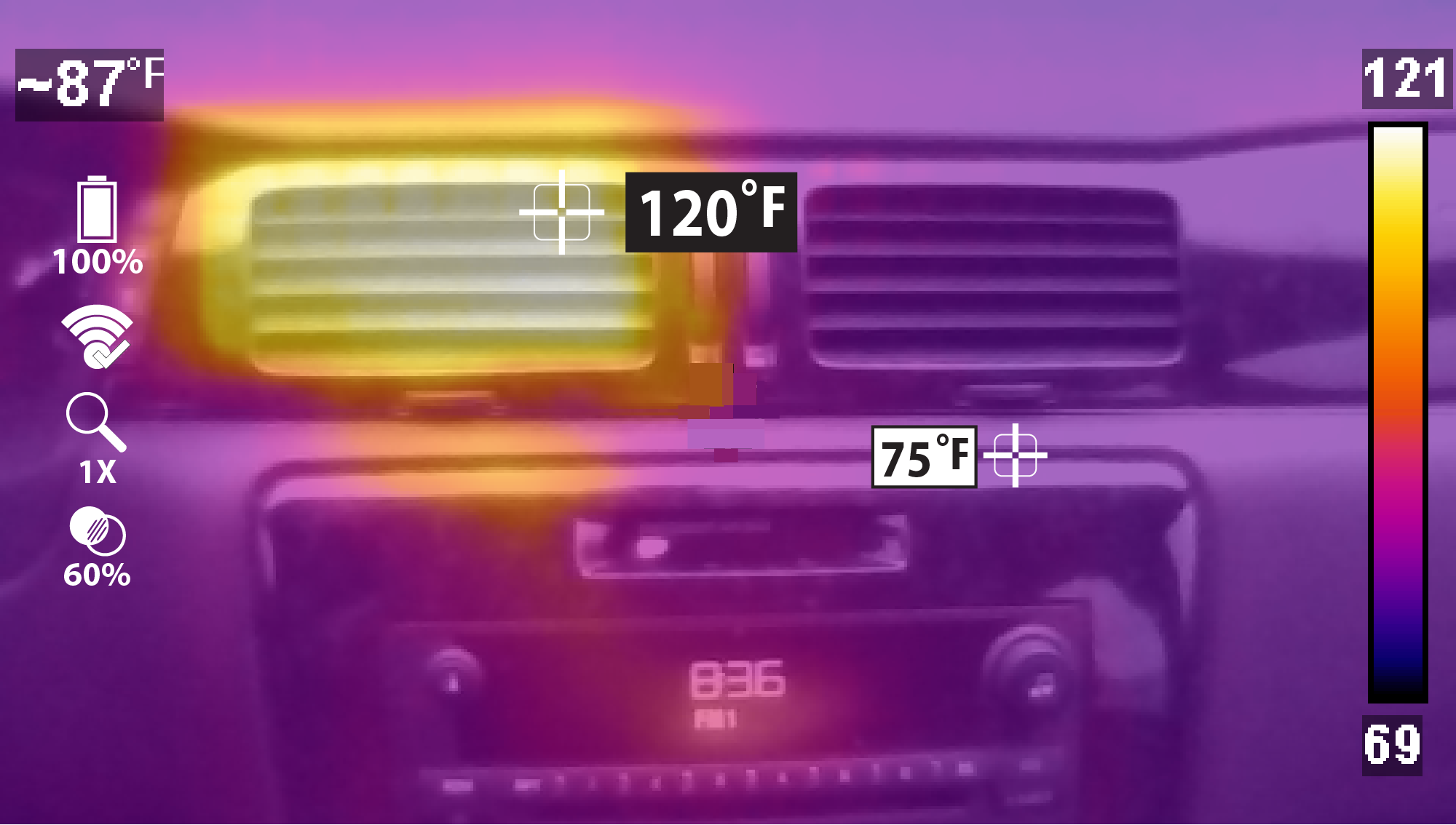
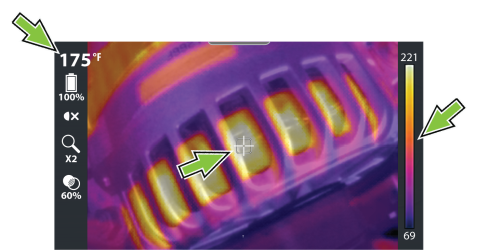
To take a thermal reading, position the point of interest in the center of the display on or near the target indicator (see image below). The target indicator measures the average temperature around the indicator, this numerical value is displayed in the upper left (see image below).
The temperature is also visually indicated within the color palette indicator on the right side (see image below). The color palette indicator shows the complete temperature range of the active measured scene including the minimum and maximum temperature values of the scene. This palette indicator is dynamic, and it is normal for the min/max temperature values to constantly change.
Display Mode- Use the Left / Right control buttons  to change display modes.
| ● | 1X Zoom |
| ● | 2X Zoom |
| ● | Picture-in-Picture |
| ● | Diffused Beam |
| ● | Split Screen |
Opacity Level- Use the Up / Down control buttons  to change opacity levels.
| ● | From 0% (Visual Light) up to 100% (Full Thermal) in 20% steps. |
Temperature Markers - Using the Freeze Image feature gives you the ability to add temperature markers to a captured image. These markers are useful when trying to display multiple temperature values, and save the image with the markers for future reference.
Taking a Picture- Activate the Trigger to save a still image  of the active screen.
Recording a Video - Press the  button to start video mode
  , then pull the Trigger to start/stop recording.
Images and videos are automatically saved to the microSD card and can be viewed in the Gallery.
LED Spotlight- Press the Y button to turn the LED spotlight ON/OFF.
Onscreen Navigational Tips - Tips are provided for select menu navigation procedures. Each tip will appear only once after turning on the Thermal Imager. Navigational
The Thermal Imager is powered by an internal rechargeable battery pack, and has a built in charger that recharges the battery when connected to a power source.
A fully charged battery pack can provide up to 4 hours of continuous operation. The battery discharge rate will vary depending on overall use and settings. For example, using the LED spotlight or a high level display brightness setting will accelerate battery discharge.
The battery pack contains no user serviceable components. Tampering with the battery pack terminals or housing will void the product warranty.
Keep the following in mind when using and handling the battery pack:
| ● | Do not short circuit battery pack terminals. |
| ● | Do not immerse the Thermal Imager or battery pack in water, or allow water to enter the Thermal Imager or battery pack. |
| ● | Do not crush, disassemble, or tamper with the battery pack. |
| ● | Do not heat the battery pack to over 100°C (212°F), or dispose of it in a fire. |
| ● | Do not expose the battery pack to excessive physical shock or vibration. |
| ● | Keep the battery pack out of reach of children. |
| ● | Do not use a battery pack that appears to have suffered abuse or damage. |
| ● | Charge the battery pack using the appropriate charger only. |
| ● | Do not use a battery charger adapter that has been modified or damaged. |
| ● | Use the battery pack for the specified product only. |
| ● | Store the battery pack in a cool, dry, well ventilated area. |
Follow all safety guidelines when handling the battery pack. Read, understand and follow all safety messages and Important Safety Information.
| 1. | Power the unit off. |
| 2. | Open the protective cover on top of the Thermal Imager. |
| 3. | Connect the USB cable to the micro USB jack. |
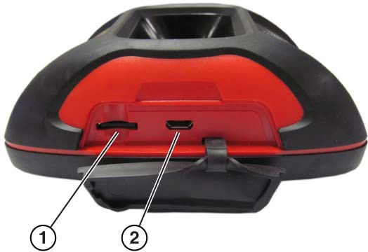
| 1. | microSD Card |
| 2. | micro USB Jack (USB power supply connection) |
Use the supplied USB power supply adapter for optimum charging results.
| 4. | Connect the USB cable to the USB power supply adapter, then connect the adapter, to a live AC power source. |
Battery charge indicator LED:
| ● | Red - indicates the battery is being charged. |
| ● | Green - indicates the battery is fully charged. |
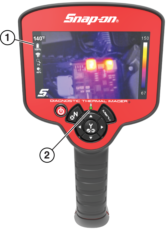
| 1. | Battery Level Icon |
| 2. | Battery Charge Indicator LED (Red-charging, Green-charged) |
When the unit is on, a battery level icon is used to indicate the charge level and status of the battery,
|
|
Battery Fully Charged Will flash when approximately 10 minutes of power remaining. |
|
|
Battery charging |


| 5. | Close the protective cover, when finished. Always keep the protective cover closed during operation. |
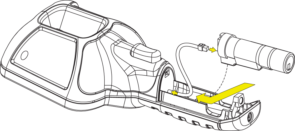
| 1. | Remove battery pack cover screw, and pull the cover back and then up to remove. |
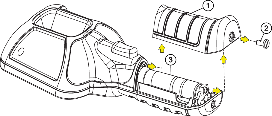
| 1. | Battery Pack Cover |
| 2. | Battery Pack Cover Screw |
| 3. | Battery Pack |
Carefully lift out the battery pack, then press down on the battery lead connector release tab and remove the connector from the battery pack.
Do not pull the battery harness out of the housing.
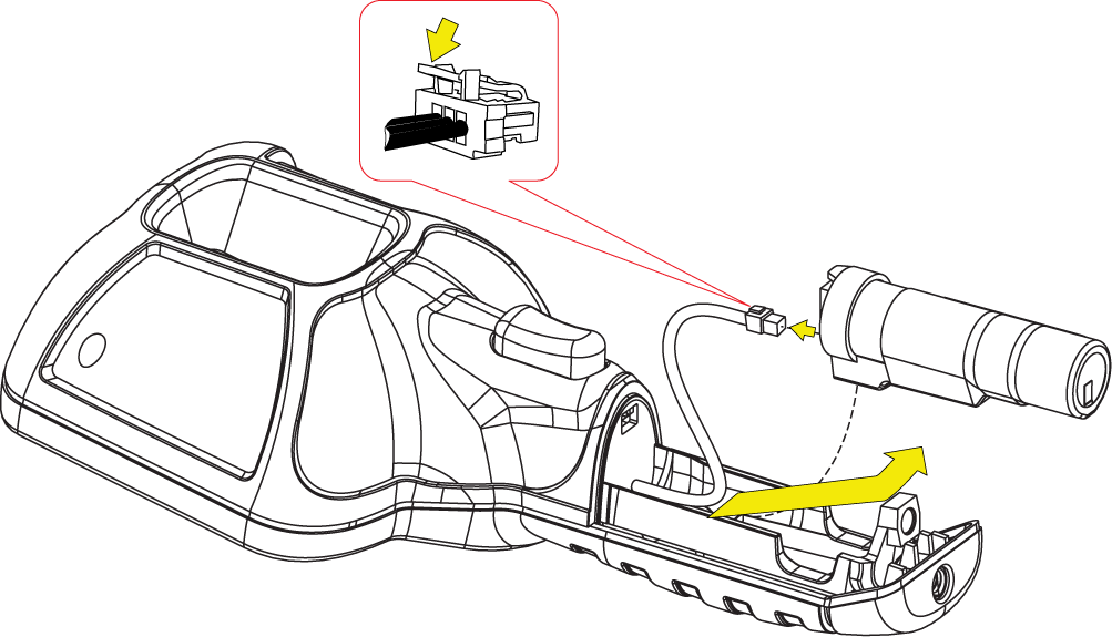
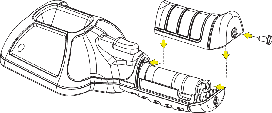
| 2. | Insert the battery connector into the battery pack, until it locks (clicks) into place. |
Do not force the battery pack into the Thermal Imager, it should set easily into place.
| 3. | Feed the slacked harness into housing, as you install the battery pack into the housing. |
| 4. | Install the battery cover. Press down until the locking tabs secure the cover. |
Contact your sales representative to order a replacement battery.
Replace the battery pack with a Snap-on replacement battery pack only.
Always dispose of a lithium-ion battery pack according to local regulations, which vary for different countries and regions. The battery pack, while non-hazardous waste, does contain recyclable materials. If shipping is required, ship the battery pack to a recycling facility in accordance with local, national, and international regulations. For additional information in the following markets contact:
| ● | United Kingdom—Electrical Waste Recycling Company at http://www.electricalwaste.com |
| ● | All other countries and regions - Contact you local battery recycling or electrical waste recycling facility for disposal instructions. |
Products bearing the WEEE logo are subject to European Union regulations.
Before you can upload images from your Diagnostic Thermal Imager+ to the Snap-on Cloud, you'll need to complete the following steps..
| 1. | Press the Menu button, then from the toolbar select the Settings icon. |
| 2. | Select Snap-on Cloud Setup from the menu. |
| 3. | Write down the Serial Number, PIN and Code that are displayed or leave the screen displayed while entering the information on https://ALTUSDRIVE.com. |
;
Your Snap-on Technician Profile is where you manage all your Snap-on companion applications, like Snap-on Cloud and Security Link. To upload images from your Diagnostic Thermal Imager+ to the Snap-on Cloud, you need to first create a Snap-on Technician Profile.
You only need to setup your Snap-on Technician Profile once. If you already have a Technician Profile skip this step.
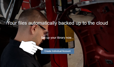
| 1. | Using an Internet connected device (PC, phone, etc) , visit https://ALTUSDRIVE.com and select Create Individual Account from the Login screen. |
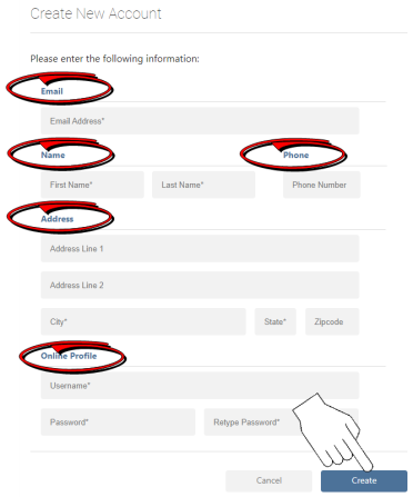
| 2. | Enter all the required information (denoted by *), and create a Username and Password, then select Create. |
A valid e-mail address is important in setting up your Snap-on Technician Profile. It allows us to keep you up to date on diagnostic tool features, services and changes associated with your profile.
| 3. | At the “Success” confirmation screen, select Done. |

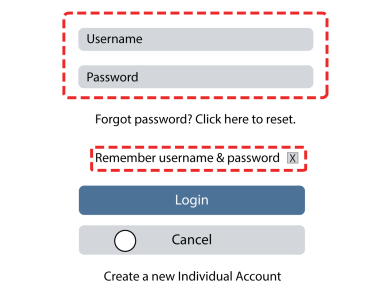
| 4. | The login window will display. Enter your Username and Password, and check the "Remember username & password" box, then click Login. |
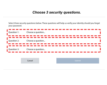
| 5. | Answer the security questions, then select Submit. |
| 6. | If needed change the language. |
Language Selection Drop-down Provided
![]()
Ensure the Thermal Imager Wi-Fi is turned on and connected to a network when setting up your profile.
Click the Device Management tab (left menu):
Select Add Device to add your Diagnostic Thermal Imager+ to your profile.
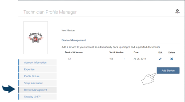
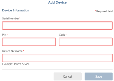
Enter the device authorization codes (as found in Step 1)
| ● | Serial Number - serial number of the device |
| ● | PIN - specific PIN associated to the device |
| ● | Code - authorization code specific to the device |
| ● | Device Name - user define name |
When finished select Save to link the device to your profile.
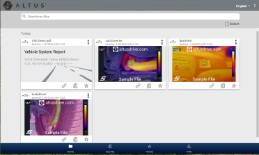
When you capture images with your thermal imager, the saved images are automatically uploaded to your Snap-on Cloud account at https://ALTUSDRIVE.com when Wi-Fi is connected.
To view your images, login at https://ALTUSDRIVE.com. The images are displayed on the start screen (or click the My Files icon at the bottom).
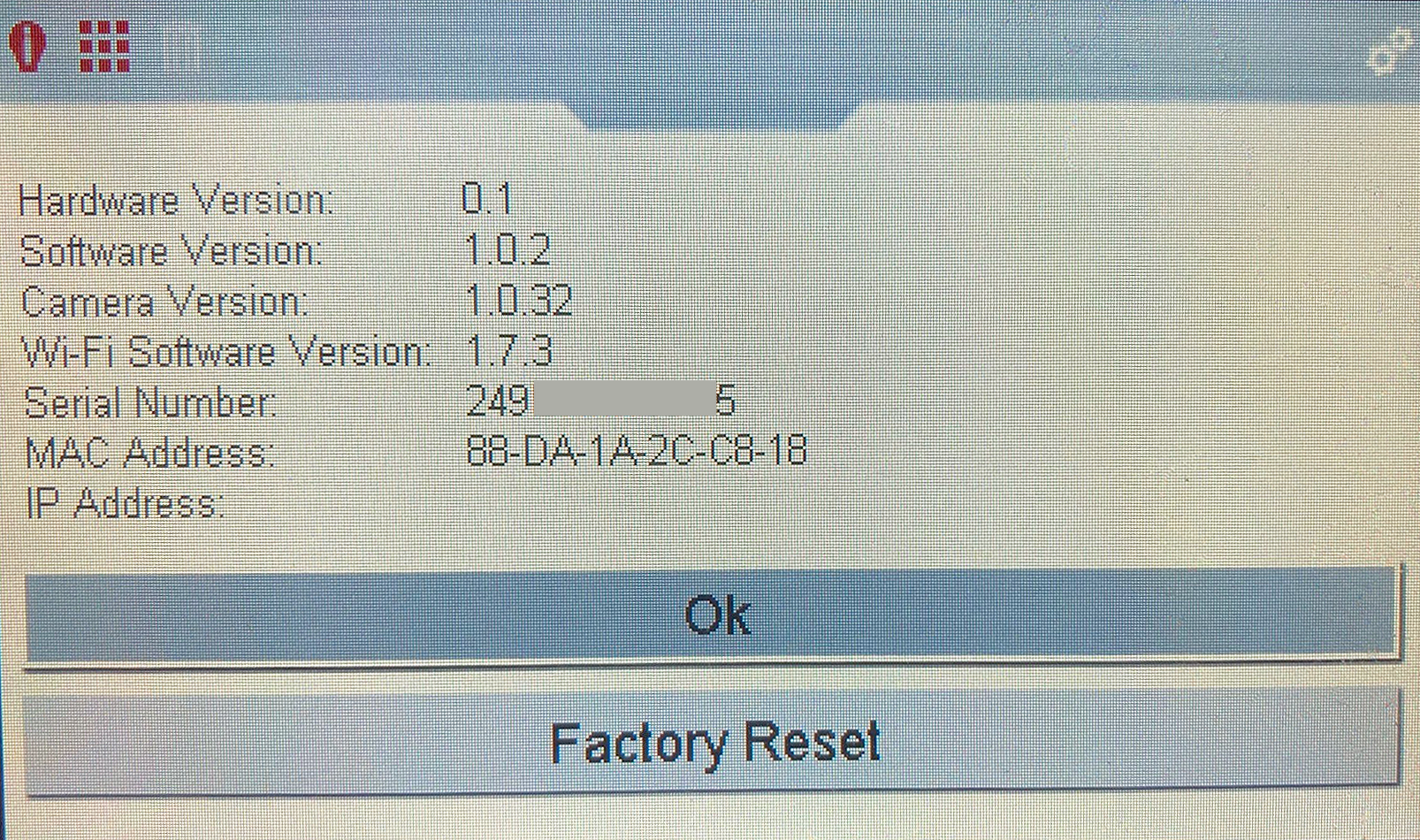
The serial number along with other system information is located in the SETTINGS menu.
| 1. | Press the Menu button. |
| 2. | Use the Left / Right control buttons to select the Settings icon from the toolbar |
| 3. | Use the Down control button to select ABOUT on the menu, and then press "Y" to open it. |
You can return to Live mode at anytime by pressing the Menu button.
|
Item |
Description / Specification |
|
Display (LCD) |
Size (diagonal): 109mm (4.3 in.) |
| Resolution: 480 x 272 pixels | |
| Digital Camera | Focus: Fixed |
| Thermal Imager | Temperature Measurement Range: -20 to 450 °C (-4 to 840 °F) |
| Color Palettes: 6 options: Iron, Rainbow, Grey-Iron, Cool-Hot, Sepia and Plasma | |
| Thermal Sensitivity (NETD): < 60mK (millidegrees Kelvin) | |
| IR Image Refresh Rate: ~7.5pfs | |
|
Radiometric Accuracy: Typical +/-3°C (+/-6 °F) or +/-3% (whichever is greater) at a distance of 30cm (near), at an ambient temperature of 20 to 25°C (68 to 77 °F), and an object temperature between 0 to 260°C (32 to 500 °F). Maximum +/-7°C (+/-13 °F) or +/-5% (whichever is greater) |
|
| Spectral Range: Longwave infrared, 8 to 14 μm | |
| IR Image Detector Type: Uncooled LWIR (Long Wave Infrared) | |
| Effective Distance: Optimum results between 50cm and 1m (19.7 and 39.4 in.) | |
| Spot Size Ratio: 22:1 | |
| LED Spotlight | Low: 7 lumens |
| Med.: 12 lumens | |
| High: 22 lumens | |
|
Image Storage Memory Capacity |
> 15000 images or 225 video recordings (total depends on the number and size of the files) |
|
Image File Format |
.bmp |
|
Video File Format |
.avi |
|
Meta Data Text File Format |
.txt |
|
USB Interface |
2.0 USB, micro USB |
| Battery | Rechargeable Lithium Ion Battery Pack (+3.6V, 2150mAh (nominal)) |
| Approximate 4 hour continuous operation, with the brightness level setting at 50% and Wi-Fi off | |
| Approximate 80% charge in 3-hours, 100% charge in less than 5-hours | |
|
USB Power Supply Rating |
5 VDC, 2A |
|
Operating Voltage (USB input) |
4.75 to 5.25 VDC |
|
Wi-Fi Features |
FCC,IC,ETSI/CE,TELEC Certified |
|
IEEE 802.11 Compliant, b/g/n with single band (2.4 GHz) |
|
|
WLAN Transmit Power: +18 dBm |
|
|
WLAN Receive Sensitivity: -97 dBm @ 1Mbps |
|
|
WPA/WPA2/WPA3-Personal, WPA/WPA2 Enterprise for Client |
|
|
Operating Altitude |
Maximum 2000 m |
|
Width |
4.80 in. (122.0 mm) |
|
Height |
9.09 in. (231.0 mm) |
|
Depth |
2.24 in. (57.0 mm) |
| Weight | 0.83 lb (376.5 g) |
|
Operating Temperature Range (ambient) |
At 0 to 90% relative humidity (non-condensing) |
|
Storage Temperature (ambient) |
At 0 to 70% relative humidity (non-condensing) |
|
Environmental Conditions |
This product is intended for indoor use only. |
|
This product is rated for Pollution Degree 2 (normal conditions). |
Use of Software is governed by the terms and conditions of the End User License Agreement. The diagnostic tool should not be initially operated until the End User License Agreement is read. Use of the device acknowledges your acceptance of the End User License Agreement. The Snap-on Incorporated Software End User License Agreement may be provided with the diagnostic tool, and is available at: https://eula.snapon.com/diagnostics
For customer and end-user access and convenience, Snap-on is providing the End User License Agreements (link above) applicable to the Snap-on Diagnostics software and platforms. These agreements or an earlier one you agreed to was either provided as hard copy or resident within the diagnostics platform software.
All pictures and illustrations shown are for reference purposes only. All information, specifications and illustrations in this manual are based on the latest information available at the time of printing and are subject to change without notice. While the authors have taken due care in the preparation of this manual, nothing contained herein:
| ● | Modifies or alters in any way the standard terms and conditions of the purchase, lease, or rental agreement under the terms of which the equipment to which this manual relates was acquired. |
| ● | Increases in any way the liability to the customer or to third parties. |
Snap‑on® reserves the right to make changes at any time without notice.
Before operating or maintaining this unit, please read this manual carefully paying extra attention to the safety warnings and precautions.
For a listing of Snap-on products that are protected by patents in the United States and elsewhere, visit: https://patents.snapon.com
For your safety and the safety of others, before you operate this device follow this link to read and understand the Important Safety Information.
Website: snapon.com/diagnostics/uk
Phone: +44 (0) 845 6066512
E-Mail: diagukps@snapon.com
Contact Form: Contact