High speed networking can be as much of a task in the workshop when it comes to modern-day vehicles as more traditional mechanical repairs can be
Our next article from Damien Coleman takes a look at a Peugeot with network corruption issues and runs through some of the steps required to complete and verify the fix.
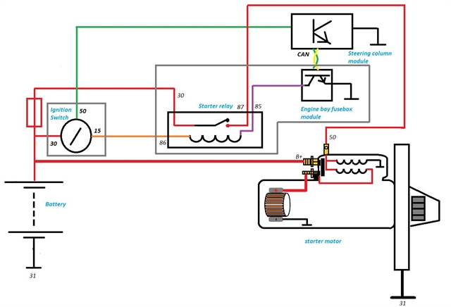
A 2011 Peugeot 207 with a 1.4 litre common rail diesel engine fitted (engine code – 8HR) was failing to start. It was found that there was no voltage present at terminal 50 of the starter motor when the ignition key was turned.
The starter motor solenoid is controlled via a surface mounted relay fitted within the engine bay fusebox module which receives a command from the steering column function module. The diagram below shows a typical circuit layout:
A full diagnostic code scan was carried out using a Snap-on VERUS Edge scan tool and a series of fault codes were retrieved relating to the data communication network and more specifically the high speed network (click here for the full list).
This isolated the high speed CAN bus network as the area of concern (click here for some key points relating to a high speed CAN network).
An Ohmmeter was connected to the data link connector to measure the total circuit resistance.
As there are two 120 Ω terminating resistors connected to the network in parallel, the total network resistance is approximately 60 Ω. This test proved the resistors were present and functional.
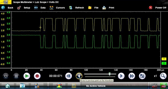
An oscilloscope was connected to the high speed network. Due to the high speed data transfer rate, the oscilloscope must be configured to display the data over a very small time base when carrying out such a test.
The ideal time base is 200 μS, and with this selection the scope will display the data captured over two hundred millionths of a second.
The voltage scale for CAN high should be 2.5 volts (recessive bit) to 3.5 volts (dominant bit) and for CAN low be 2.5 volts (recessive bit) to 1.5 volts (dominant bit). Both channels should be set to the five volt scale.
The waveform results from the test indicated a network fault with the most likely reason being a faulty control module corrupting the network.
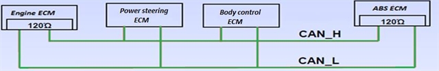
A wiring diagram was used to identify the applicable modules on the CAN bus network. A simplified version of the block diagram is shown below with the inclusion of the terminating resistors:
Each module was disconnected in turn and the oscilloscope screen was observed.
When the ABS control module was disconnected the network resistance increased to 120 Ω as it did when the engine control module was disconnected.
This is due to the removal of one of the terminating resistors from the network, and it proves their location.
When the power steering control module was disconnected the network signal returned to normal.
This indicated a fault with the CAN chip within the module. The module and steering rack were replaced and all fault codes were erased.
A full system diagnostic scan with the VERUS Edge showed that the fault had been rectified so the final test was to connect the oscilloscope to the CAN network once more and the waveform showed the network to be functioning correctly:
Date posted: 9 February 2017