Mutual induction is the fundamental operating principle of a modern ignition coil on a spark ignition internal combustion engine.
A spark is required to ignite the mixture of fuel and air within the combustion chamber. A conventional ignition coil has a primary and secondary winding and a soft iron core.
The strength of the ignition spark is dependent upon three basic parameters:
- The amount of current flowing in the primary winding
- The turns ratio between the primary and secondary winding
- The rate of change of magnetic flux (field)
Once current flows in the primary circuit, a strong magnetic field is built up around the primary winding. This build-up is gradual owing to the inductance associated with the winding.
When the current flow is switched off in the primary circuit the magnetic field collapses and a voltage is induced into the secondary winding.
This voltage is “stepped up” because the secondary winding contains many more turns in comparison to the primary winding, in the order of 1:100 as a ratio.
The secondary circuit is deliberately incomplete. A gap exists at the spark plug and as the current flow will complete the circuit and flow to a ground potential the gap is bridged electronically.
The air and fuel mixture between the gap at the spark plug becomes ionised and combustion takes place.
A flame front propagates from the spark plug and ignites the air-to-fuel mixture in a uniform and controlled manner within the combustion chamber.
This combustion creates a pressure wave which acts on top of the piston and pushes it down the cylinder, not too dissimilar to a cyclist pushing down on a bicycle pedal.
This reciprocating force is converted to rotation force by the connecting rod and the crankshaft rotates.
A diode is fitted to modern direct ignition coils to eliminate the possibility of a spark being created in the secondary circuit when the current begins to flow in the primary winding.
The switching on and off of the primary circuit current is controlled by semi-conductors called transistors.
A transistor is used to complete the primary circuit by providing the current with a path to ground.
The graphic below shows the basic components of a modern ignition system.
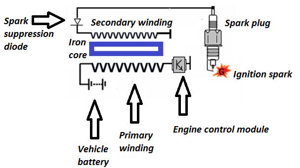 |
| Figure 1 |
The images below show oscilloscope waveforms, captured on a Snap-on VERUS Edge scan tool, from a Vauxhall Vectra with a faulty transistor in the engine control module.
This fault resulted in a slow switch-off of the primary circuit current so a weak spark was present in the secondary circuit.
Figure 2 shows the current flow through the primary circuit and demonstrates the slow drop-off.
Figure 3 shows the vehicle after repair, and a quick and sharp current switch is evident, validating that the fault has been fixed.
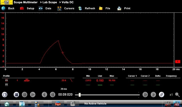 |
| Figure 2 |
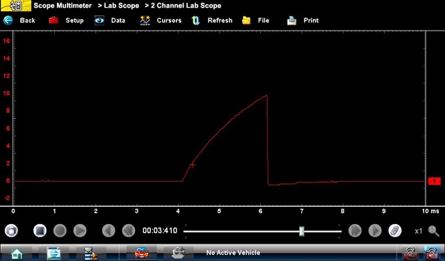 |
| Figure 3 |