This month’s Technical Focus article details a fix on a Yaris with a chequered history of battery and alternator problems…
By Damien Coleman
A 2002 Toyota Yaris with a one litre spark ignition engine had been out of use for several months and required assistance to start the engine when it was to be driven again.
The owner used another vehicle to jump-start it but there was some confusion and a number of fuses and fusible links were blown. At this point the owner decided not to attempt any further repairs himself.
Six fuses and two fusible links needed to be replaced before the vehicle would start. The vehicle battery was also replaced due to a faulty cell. Although the vehicle then started, the charge warning light was illuminated.
After an initial inspection the alternator was found to providing zero output to the vehicle battery/electrical system. The alternator was removed from the vehicle for bench testing.
All six power diodes were tested and validated to be functioning correctly. Each diode conducted in the forward direction and opposed current flow in the reverse direction.
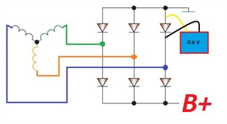

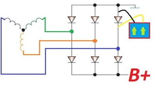

When testing diodes on the diode test function, a voltage drop of 0.5–0.6 volts in the forward direction and open circuit in the reverse direction indicates a good diode. Note the connection of the test leads in the diagrams above.
Next the rotor field winding was tested and the fault was identified here; the winding was open circuit. The resistance of an operational field winding is approximately 3 to 5 Ohms.
The principle of operation of the alternator is as follows: a rotating magnetic field (rotor) induces an electrical current into stationary conductors (stator), and the induced voltage is dependent on the following factors:
- The strength of magnetic field
- The speed at which the magnetic field rotates
- The number of turns in the stator
An open circuit rotor winding will result in the alternator not producing a charge, so the alternator was replaced. The cost of the exchange was less than the cost to repair the original unit.
Once the alternator was replaced a new problem became apparent – the engine would start and run, but once the alternator began charging the engine would run rough and cut out.
The first task was to identify the reason for the engine shutting down. An oscilloscope was connected to the fuel injector control wires and just before the engine stalled the engine control module (ECM) deactivated the injectors.
This engine is fitted with an inductive crankshaft and camshaft sensor. As a voltage spike could corrupt the output from an inductive sensor, the oscilloscope was connected to both sensors to investigate the signal integrity.
Both signals were clean and displayed as expected so the engine management system was interrogated for faults and the following fault code was retrieved:
- P1315: Igniter circuit malfunction cylinder 4
As this fault code initially didn’t appear to be a concern when the charging system was considered, it was temporarily dismissed because the engine performed perfectly with the alternator disconnected.
It was expected that a faulty ignition coil would be evident regardless of the vehicle charging system operating or not.
Misfire monitors are run under certain operating conditions but this fault still didn’t seem to contribute to the rough running and cutting out.
Again, due to the history of the vehicle, the charging system was investigated. A current clamp was connected to the main lead from the alternator to the vehicle battery (B+), and a second test was carried out with the oscilloscope coupled to AC to analyse the diode ripple.
It was expected that a faulty diode or a voltage spike would be observed, which was causing the ECM to shut down. Both waveforms are below:
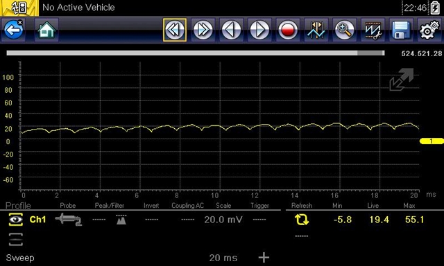
The above image shows a current output of approximately 20 Amps (under low electrical load) and the waveform is clean without any glitches or voltage spikes.
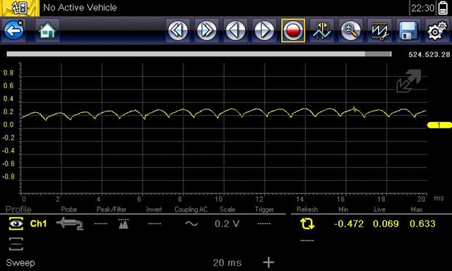
This image shows a diode ripple test with the oscilloscope coupled to AC. The rectifier looks to be preforming correctly and the ripple is less than 200 millivolts so from this data we can deduce that the alternator is operating correctly.
The only clue to assist with the repair is the fault code for the ignition coil (P1315). This ignition system uses a driver-in-coil setup.
A signal is sent from the ECM to the ignition coil to switch on the primary current flow. The pulse width of the signal varies depending on dwell period requirements. A feedback signal from the ignition coil is monitored by the ECM.
The diagram below shows the circuit layout. Each ignition coil has an ignition on supply, ground and feedback wire, all of which are connected in parallel to each individual ignition coil. Each ignition coil then has a separate signal wire from the ECM.
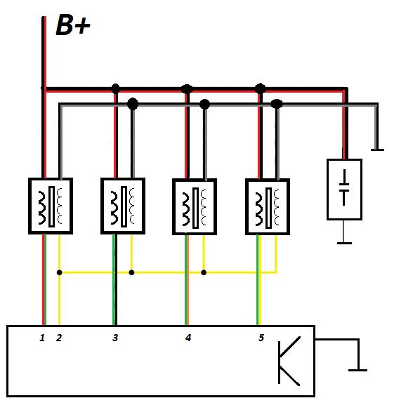
An oscilloscope was connected to cylinder 4’s ignition coil to monitor the entire circuit:
- Yellow trace: Feedback from ignition coil
- Green trace: Cylinder 4 command signal from ECM
- Blue trace: Supply voltage circuit
- Red trace: Ground circuit
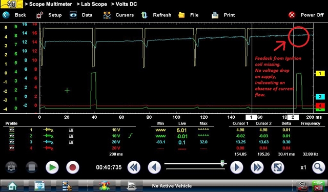
Rather than relying on the vehicle alternator to increase the system voltage, a DC power supply with a variable (controllable) voltage output was connected to the battery. This allowed the vehicle system voltage to be precisely controlled for testing purposes.
It is evident from the waveform that as the system voltage reaches 13.63 Volts there is no longer a feedback signal from the ignition coil.
The characteristic voltage drop on the supply when current is flowing through the primary winding is also missing.
This is an indication that the ignition coil driver circuit is not switched on, at this point the engine runs rough and cuts out.
From the waveform below we can see that after the feedback signal is lost the ECM switches off the fuel injector:
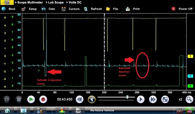
- Yellow trace: Feedback from ignition coil
- Green trace: Cylinder 4 command signal from ECM
- Blue trace: Cylinder 4 injector control
A new ignition coil was fitted to the vehicle and the fault code was cleared. The vehicle operated as expected with the charging system connected and working correctly.
A block diagram of the internal circuitry of the ignition coil is shown below:
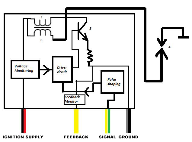
- Primary winding
- Secondary winding
- Primary circuit driver control
- Spark plug
The fault with this ignition coil was in the voltage monitoring circuit, as once the system voltage exceeded 13.6 volts the internal circuitry would not allow the driver control circuit to be switched on.
As this would be considered to be normal charging voltage it can be seen that this voltage monitoring circuit erroneously detected the voltage to be greater than the voltage actually applied to the ignition coil.
This is why the vehicle preformed correctly at normal battery voltage with the alternator disconnected (<13.6 volts).
Date posted: 26 April 2016