
Getting Started

Features and Operations Overview
Contents
Installing the Battery & Powering Up
Always dispose of the battery pack according to local regulations, which vary for different countries and regions. The battery pack, while non-hazardous waste, does contain recyclable materials. If shipping is required, ship the battery pack to a recycling facility in accordance with local, national, and international regulations. Contact your sales representative for details.

For additional information contact: Australian Battery Recycling Initiative https://www.batteryrecycling.org.au/
Connecting an External Monitor
|
Scanner (Common Icons) |
|||
|---|---|---|---|
|
Not all Icons are shown. Icons are not applicable to all tools. |
|||
|
|
Home - Return to Home screen, or open Quick- Access menu |
|
Accept - Accepts the highlighted selection |
|
|
Next / Forward |
|
Back / Last |
|
|
Save - Saves the active information to memory. |
|
Automatic ID - Automatically completes the identification process, once connected and make/year are entered. |
|
|
Single Selection (List) - Select / Deselect single item from list |
|
Multi-Selection (List) - Select / Deselect all items in a list |
|
|
Menu View - Toggle between categorized / |
|
|
|
|
Pause - Pauses active data collection. |
|
Start (Capture) - Resumes active data collection. |
|
|
Clear - Erases all the PID data in the buffer and restarts data collection. |
|
Custom Data List - Allows you to choose which PIDs display. |
|
|
Trigger - Allows you to set, arm, and clear PID triggers |
|
Change View - Toggle data display between list or graph. |
|
|
Zoom - Incrementally increases and decreases the scale of the data displayed. |
|
Lock - Locks PIDs to the top of the list. |
|
|
Step Forward - Allows forward movement in singular steps. |
|
Step Back - Allows backward movement in singular steps. |
|
|
Skip Forward - Allows forward movement in multiple steps. |
|
Skip Back - Allows backward movement in multiple steps. |
|
|
PID Alarm - Display visual indicators for two state PIDs |
|
Sort - Toggles the alpha order of a list. |
|
|
Data List Selector - Choose data list during functional test |
|
|
|
|
Diagnose - Opens Intelligent Diagnostics for the selected code. |
||
|
Code Scan |
|||
|
|
Refresh - Restarts the code scan |
|
System - Opens the main menu of the system selected |
|
Oil Specs & Resets |
|||
|
|
Fluid Capacity - Displays OEM engine oil specifications and capacity information. |
|
Reset Procedure -Displays OEM manual service indicator reset information. |
|
|
|
- |
- |
|
Tire and Wheel Service |
|||
|
|
Displays TPMS indicator reset instructions, to perform a manual reset of the TPMS indicator. |
|
Opens the TPMS test related Scanner menu. Options may include, view and clear codes, display data, and access functional tests using the diagnostic tool. |
|
|
Displays TPMS service information. |
|
Displays OEM tire and wheel specifications. |
|
Wi-Fi Icons |
|||
|
|
Indicates Wi-Fi is ON and Connected |
|
Indicates Wi-Fi is ON, Low Signal |
|
|
Wi-Fi On - Not Connected. |
|
Opens Wi-Fi Test screen |
|
Previous Vehicles and Data Icons |
|||
|
|
Delete - Deletes the selected item (menu dependent) |
|
View - Displays associated vehicle information and data file attachments |
|
|
Activate Vehicle - Starts the vehicle identification process, of the selected vehicle |
|
Edit - Modify vehicle information (VIN, odometer, etc) |
|
Software Updates (via Wi-Fi) |
|||
|
|
Down arrow - (displayed in upper status bar) indicates a software upgrade or update is occurring |
|
Check mark - (displayed in upper status bar) indicates when the update is ready to be installed. |
|
|
Exclamation mark - (displayed in upper status bar) indicates the update was interrupted (e.g. Wi-Fi connection was lost, or the Internet connection dropped out.) |
|
|


Fast-Track® Intelligent Diagnostics
 Wi-Fi Required
 Scope / Multimeter

Wi-Fi Required
 OBD-II/ EOBD

 Tools (Device Settings)
Finding the Serial Number / Software Version
Wi-Fi Required
Wi-Fi Required
Security Link (Secure Gateway)
Wi-Fi Required
Access secure vehicle gateway systems using your Snap-on diagnostic tool.
What you need to do:
| 1. | Use a compatible Snap-on diagnostic tool with current software and Wi-Fi turned on. |
| 2. | Have a Snap-on Technician Profile (see video above) |
| 3. | Link your diagnostic tool to your Snap-on Technician Profile. |
| 4. | Create the Secure Gateway OEM account you need (if applicable) and then add those credentials to your Snap-on Technician Profile. |
The ShopStream Connect™ (SSC) software is a free PC-based software that extends the capabilities of your diagnostic tool
-
View, Print, and Manage data saved from your Diagnostic tool.
-
Move and copy your data between the diagnostic tool and your PC.
-
View and Print trouble codes saved with select diagnostic tools. This allows you to share the data in a report format with vehicle owners or other technicians.
-
Add or edit notes and comments to diagnostic tool data files.
-
Download and install diagnostic tool software updates and upgrades.
|
Item |
Description / Specification |
|
Touch Screen |
Capacitive Touch Panel |
|
Display |
10.1 inch diagonal, TFT Color LCD |
|
1024 x 600 resolution WSVGA |
|
|
Battery |
7.2 VDC 6000 mAh (43.2 Wh) Rechargeable lithium-ion battery pack |
|
Approximately 8hr @ 50% brightness run time |
|
|
Approximately 4.5 hour charge time |
|
|
Power Supply (included) |
Supply Rating; 15VDC, 1.6A 24W |
|
Power Supply(optional) |
When using USB-C power, the power supply must be USBC PD3.0 Compliant Charger Minimum 9V @ 24W |
|
DC Operating Voltage |
10 to 20VDC |
|
HDMI Output |
Micro-HDMI Type D (Micro) connector. Supports External LCD Monitor Resolutions: ☻ 800 x 600 60Hz ☻ 1024 x 600 60Hz |
|
Width |
12.2 in. (309 mm) |
|
Height |
7.5 in. (190 mm) |
|
Depth |
1.6 in. (40.7 mm) |
|
Weight (including battery): |
3.1 lb (1.4 kg) |
|
Operating Temperature Range (ambient) |
At 0 to 90% relative humidity (non-condensing) |
|
Storage Temperature (ambient) |
At 0 to 70% relative humidity (non-condensing) |
|
Operating Altitude |
Maximum 2000 m |
|
Environmental Conditions |
This product is intended for indoor use only |
|
This product is rated for Pollution Degree 2 (normal conditions) |
| Function | Range | Accuracy/Comments |
|---|---|---|
| Signal Measurement | Ch. 1— (yellow jack) Ch. 2— (green jack) | Each channel input is referenced to common ground (GND— black jack). |
| Sample Rate | For 50µS sweep 6 (MS/s) For 100µS sweep 3 (MS/s) For all other sweeps 1.5 (MS/s) | Continuous sampling, (MS/s) = mega samples per second |
| Band Width | 3 MHz | 3 db point @ 3 MHz |
| Zoom In |
Supported for 1ms sweep and above |
Available levels are determined by sweep setting (Max. + X15) |
| Input Impedance | 10 MΩ @ DC 4 kΩ @ 3 MHz | Channel 1 and 2 |
|
Category Rating |
CAT I |
|
| VDC (Full Scale) | 100mV–400V | Do not measure greater than 75VDC |
| VAC (Full Scale) | 100mV–400V | Do not measure greater than 50 VAC (rms). |
| Low Amp Probe | 20A scale (100mV/Amp) 40A scale (10mV/Amp) 60A scale (10mV/Amp) | Connect the positive (+) Amp Probe lead to the yellow jack on the diagnostic tool for values on Ch.1, or to the green jack for values on Ch. 2. Connect the negative (–) lead to GND (black jack)1*. |
|
1*. Do not use the Low Amp Probe to measure current on conductors at a potential greater than 46VAC peak or 70VDC. |
||
| Function | Range | Accuracy/Comments |
|---|---|---|
| Signal Measurement | Ch. 1— (yellow jack) Ch. 2— (green jack) | Each channel input is referenced to common ground (GND— black jack). |
| Sample Rate | 1.5 MSPS | Continuous sampling, (MS/s) = mega samples per second |
| Band Width | 3 MHz | 3 db point @ 3 MHz |
| Input Impedance | 10 MΩ @ DC 4 kΩ @ 3 MHz | Channel 1 and 2 |
|
Category Rating |
CAT I |
|
| VDC (Full Scale) | 75VDC | Do not measure greater than 75VDC |
| VAC (Full Scale) | 50VAC | Do not measure greater than 50 VAC (rms). |
| Low Amp Probe | 20A scale (100mV/Amp) 40A scale (10mV/Amp) 60A scale (10mV/Amp) | Connect the positive (+) Amp Probe lead to the yellow jack on the diagnostic tool for values on Ch.1, or to the green jack for values on Ch. 2. Connect the negative (–) lead to GND (black jack)1*. |
|
1*. Do not use the Low Amp Probe to measure current on conductors at a potential greater than 46VAC peak or 70VDC. |
||
| Function | Range | Accuracy/Comments |
|---|---|---|
| Signal Measurement | Ch. 1— (yellow jack) | Input is referenced to common ground (GND— (black jack) |
| VDC (Full Scale) | 75VDC | Do not measure greater than 75VDC |
| VAC (Full Scale) | 50VAC | Do not measure greater than 50VAC (rms) |
| Signal Measurement Input Impedance | 10 MΩ | |
|
Category Rating |
CAT I |
|
| Ohm Measurement Diode Test Continuity Test | Ch. 1— (yellow jack (–)) Ch. 2— (green jack (+)) | |
| Ohms | 40 Ω—4 MΩ | Fixed scales or auto ranging |
| Glitch Capture | Approximately 50 µS | |
| Diode test | 2V scale |
| Item | Description / Specification |
| Communications | Wireless Bluetooth® 2.1 Technology |
| Operating Range | Approx. 50 feet (15.24 m) |
| USB Power | Max. 5V @ 0.9A |
| DC Operating Power |
Scan Module Model EESM3060B: 8-32 VDC, Max. 10W, Scan Module Model EESM317A: 8-32 VDC, Max. 6.5W |
|
Width |
1.87 in. (47.5mm) |
| Height | Ch. 0.95 in. (24.2mm) |
| Depth | 4 in. (101.7mm) |
| Weight | A0.22 lb (100 g) |
| Operating Temperature Range (ambient) | At 0 to 80% relative humidity (S9 and S10 were done in 80% RH environment) |
|
Storage Temperature (ambient) |
At 0 to 70% relative humidity (non-condensing) –4 to 140°F (–20 to 60°C) |
|
Operating Altitude |
This product is intended for indoor use only |
|
Environmental Conditions |
This product is rated for Pollution Degree 2 (normal conditions) |
|
Certifications |
Scan Module Model EESM317A
Control Numbers: 5029505, 4001705, 5034877 Conforms to UL STD UL 201, 62368-1 Certified to CSA STD C22.2# 62368-1 |

For your safety and the safety of others, before you operate this device follow this link to read and understand the Important Safety Information.
Website – https://www.snapontools.com.au/diagnostics/
Phone
-
AU: 1800 810 581
-
NZ: 0800 762 766
E-Mail –sota.diagnostics@snapon.com
Helpdesk – https://www.snapontools.com.au/diagnostics/helpdesk/
ShopStream Connect™ – snapontools.com.au/diagnostics/downloads
Vehicle Coverage Guide / Accessories Information
Snap-on® Cloud – altusdrive.com
Training Information and Videos
Online Store – https://www.snapontools.com.au/terms-and-conditions/
Use of Software is governed by the terms and conditions of the End User License Agreement. The diagnostic tool should not be initially operated until the End User License Agreement is read. Use of the device acknowledges your acceptance of the End User License Agreement. The Snap-on Incorporated Software End User License Agreement may be provided with the diagnostic tool, and is available at: https://eula.snapon.com/diagnostics
For customer and end-user access and convenience, Snap-on is providing the End User License Agreements (link above) applicable to the Snap-on Diagnostics software and platforms. These agreements or an earlier one you agreed to was either provided as hard copy or resident within the diagnostics platform software.
Snap-on, Sun, Fast-Track, SureTrack, ShopStream, and ShopKey Pro are trademarks registered in the United States and other countries of Snap‑on Incorporated. The aforementioned trademarks are not an inclusive list of all the registered trademarks that may be used within this content, those trademarks are a partial list of all the trademarks registered in the United States and other countries of Snap‑on Incorporated. All other marks are trademarks or registered trademarks of their respective holders.
The Bluetooth word mark and logos are registered trademarks owned by :Bluetooth SIG, Inc. and any use of such marks by Snap-on Incorporated is under license.
All pictures and illustrations shown are for reference purposes only. All information, specifications and illustrations in this manual are based on the latest information available at the time of printing and are subject to change without notice. While the authors have taken due care in the preparation of this manual, nothing contained herein:
-
Modifies or alters in any way the standard terms and conditions of the purchase, lease, or rental agreement under the terms of which the equipment to which this manual relates was acquired.
-
Increases in any way the liability to the customer or to third parties.
Snap‑on® reserves the right to make changes at any time without notice.
For a listing of Snap-on products that are protected by patents in the United States and elsewhere, visit: https://patents.snapon.com
Visit the Knowledge Base for additional Information.
FAQ's & Additional Information
Select a category to learn more...
Contact your Snap-on representative, or see Diagnostic Accessories
Yes, Visit your Snap-on online store, or contact your Snap-on representative.
Yes, Contact your Snap-on representative, or see Diagnostic Accessories
See the video (Features & Controls) in the section above.
Use either charging method below.
1. Connect the supplied AC power supply to the power supply (barrel jack) located on the top of the tool.
2. Using a cable, connect a USB power supply to the USB-C port located on top of the tool. (obtain cable and power supply locally, specification below)
-
USB-C Power Supply Specification : USBC PD3.0 Compliant Minimum 9V @ 24W
Yes, Visit your Snap-on online store, or contact your Snap-on representative.
Yes, Contact your Snap-on representative, or see Diagnostic Accessories
ATTENTION: Only use the applicable Snap-on replacement battery pack.
The Battery Status Indicator LED (located on the top of the tool) indicates battery status.
|
Battery Status LED |
|
|
Green - Fully charged / power being supplied by the AC power supply. |
|
|
Red - Charging |
|
|
Amber - Fault Mode, battery temperature above 104°F/40°C. Allow the tool and battery to cool down before continuing operation. |
See the video (Installing the Battery & Powering Up) in the section above.
TRITON power supply - Snap-on P/N 2-62066A.
Original Mftr Information - APS P1415 AC Adapter Model: KSAS0251500200D5
Specs:
| ● | Input: 100-240V~50/60Hz 0.9A |
| ● | Output: 15V - - - 2.0A |
ATTENTION: Not all scan tool AC power supplyss are compatible. Using the incorrect power supply can prevent the battery from charging or cause issues during software upgrade installations. Only use the applicable power supply for your tool.
Visit your Snap-on online store, or contact your Snap-on representative.
Contact your Snap-on representative, or see Diagnostic Accessories
The MicroSD card contains the operating system files and user data files (e.g. screen captures and scanner data recordings).
ATTENTION: Do not remove the Micro SD card. The diagnostic tool will not operate without the MicroSD card installed.
The USB-C port can be used to:
-
Power the unit and charge the battery
-
USB-C Power Supply Specification : USBC PD3.0 Compliant Minimum 9V @ 24W (obtain locally)
-
-
Transfer saved data files to a personal computer, using the Connect to PC function in Tools. See the video (Connect-to-PC / The "S" Button) in the section above.
See the video (Connecting an External Monitor) in the section above.
HDMI cable (Standard to Type-D adapter cable) is not provided, please obtain locally.
-
Supported LCD Monitor Resolution : 800 X 600 60Hz, 1024 X 600 60Hz
The USB-C adapter cable is to supply power to the scan module when pairing or updating the scan module firmware. Connect the USB cable between the USB-C port on the tool and the scan module. See the FAQ Scan Module & Vehicle Data Connection for additional information on pairing and firmware updates.
Obtain a USB-C data cable (not provided) and connect the tool to a PC.
See the video (Connect-to-PC / The "S" Button) in the section above.
"Not Connected", whats wrong?
When troubleshooting connectivity issues, first review the scan module LED status and hardware status icons for possible causes. Make sure the scan module is powered on, paired and able to communicate.
Scan module operations can be impacted when signal interference, or some other condition, disrupts or impairs the wireless communication network.
See the video (Pairing the Scan Module) in the section above.
Helpful Tips When Pairing
-
Power the tool using the AC power supply
-
Ensure the scan module is powered on. Connect the scan module to a vehicle data link connector (DLC), or use the supplied USB cable to connect the scan module the USB port on the tool.
-
The green LED on the scan module is illuminated when power is being supplied to the scan module by a vehicle DLC. The blue LED is illuminated when power is being supplied by USB connection.
-
The LEDs on the scan module indicate communication and power status. The following LED descriptions apply only when the scan module is powered by the vehicle DLC (unless otherwise noted).
LED Indicators:
| ● | GREEN |
| – | Off - scan module is not being powered |
| – | On Continuous - scan module has power, but is not communicating |
| – | Flashing - scan module has power, and is communicating |
| ● | RED |
| – | Off - normal state, no errors detected |
| – | On Continuous - communications error detected |
| – | Flashing - internal self-test in process, will go out once the test completes |
| ● | BLUE |
| – | Off - no connection |
| – | On Continuous - USB power cable connected |
| – | Flashing - scan module has power, and is communicating |
In addition to onscreen messages, the scan module uses audible tones to alert you of connection status.
Audible Alerts:
-
Initial power on - (single 100ms “beep”)
-
Communication terminated, scan module still connected to vehicle DLC - (After losing communication, will continuously beep at two different frequency's every 10 seconds.)
-
Communication terminated with diagnostic tool (out of range) - (After losing communication, will continuously beep at two different frequency's every 10 seconds.). Diagnostic tool will also display a message “trying to re-establish communication”
If other alerts occur (series of “beeps”) this may indicate a communication error. Follow the onscreen instructions, to identify and resolve the issue.
Scan module firmware updates (when available) are delivered with diagnostic software updates/upgrades. Upon starting the Scanner function, initially after a software update or upgrade has been installed, a message may be displayed to inform you an update is available.
Helpful Tips when Updating Firmware (ensure the following):
-
The diagnostic tool is ON.
-
Power the tool using the AC power supply
-
The scan module is disconnected/not communicating with a vehicle.
-
The supplied USB cable is connected between the tool and the scan module providing the scan module power.
-
To follow all screen prompts.
vehicle communication to the display?
No, The scan module USB port is only used to provide power to the scan module during a scan module firmware update, or when pairing.
The USB port is not for vehicle communication.
Yes, You can connect to ethernet equipped vehicles with a standard 16 pin OBD-II diagnostic link connector (DLC).
No, The diagnostic tool Wi-Fi connection is only for the purpose of connecting to the Snap-on Diagnostics Information service in order to use features like Fast Track Intelligent Diagnostics, and the Snap-on Cloud.
The Wi-Fi connection does not provide access to the conventional Internet or any other services.
It is recommended to keep Wi-Fi on and connected at all times.
See the video (Connecting to Wi-Fi) in the section above.
WPA2 and WPA3 Support Information
(Mobile Device Connection)
ATTENTION: WPA3 Wi-Fi encryption is not supported.
When setting up your WI-Fi connection, ensure it is configured to use only WPA2 (Not WPA2/WPA3 or WPA3 or any similar combination).
Mobile device hot spot connection guidelines:
iOS (Typical)
Click on “Settings” 
Click on “Personal Hotspot” 
Turn ON “Maximize Compatibility”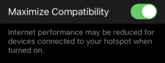
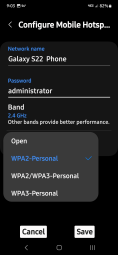
Android (Typical)
| 1. | Click on “Wi-Fi Settings” |
| 2. | Click on “Configure Mobile Hotspot” |
| 3. | Select “WPA2-Personal” |
This tool supports 2.4GHz & 5GHz.
Router Information
Router compatibility and setup are important factors to check when trying to determine connectivity problems. Although we have tested this device at the factory to verify connectivity, we cannot guaranty its connectivity with your specific equipment. There may be some situations that require your time for router connection troubleshooting and/or additional consultation and equipment. Snap-on Incorporated is not responsible for any costs incurred for any additional equipment, labor or consultation charges or any other costs that may result from correcting non-connectivity issues with this device.
Routers using WEP encryption are not supported and should not be used.
Verify the following router settings BEFORE you begin troubleshooting a non-connectivity or “No Connection” problem. After each check, make any corrections as necessary then retest for connectivity. Contact your IT administrator or ISP for assistance.
| 1. | Check your router connection and if applicable, the remote wireless access point connection. |
| 2. | Clear saved Wi-Fi networks |
| 3. | Verify: |
| a. | Router is configured to use Dynamic Host Configuration Protocol (DHCP), not a static IP address. |
| b. | Router and/or settings for this device are configured to 2.4GHz. 5GHz is supported, however 2.4GHz is the preferred setting as it provides more range. |
| c. | Router is configured to B/G and/or N standard wireless networks to 2.4GHz. 5GHz is supported, however 2.4GHz is the preferred setting, as it provides more range. See your router "User Guide" for setup, connection and troubleshooting procedures. |
Routers using WEP encryption are not supported and should not be used.
| 4. | Check for router firmware and update to current version, if applicable. |
| 5. | Restart or reset the router. See your router "User Guide" for procedures. |
| 6. | Connect to a different router. |
Troubleshooting Chart
|
General -Troubleshooting |
||
|---|---|---|
|
Problem |
Corrective Action |
|
|
No Connection |
Your Authorized Access has expired |
Contact your sales representative. |
|
Access may be temporarily unavailable |
Try to access the function at a later time as updates may be in process. |
|
|
Wi-Fi radio is turned Off |
1. From the Home screen, navigate to Tools > Settings > Configure Wi-Fi. |
|
|
Not connecting to a network |
1. Clear your saved Wi-Fi networks.
|
|
|
Wi-Fi connection drops off or disconnects intermittently |
Wi-Fi Signal strength insufficient |
Check Wi-Fi signal strength - out of range or interference. Move closer (within 50 Ft. (15 M) or into a direct open sight-line of the router or if applicable, remote wireless access point. Eliminate interference from overhead lights, windows, walls, other wireless devices, metal objects and devices that emit electrostatic discharge. |
|
Router overloaded |
Disconnect/disable other Wi-Fi devices connected to the router. |
|
See the video ( System Settings) in the section above.
Select (Home Screen > Tools) to access system settings.
See the video (Connect-to-PC / The "S" Button) in the section above.
Select (Home Screen > Tools > Configure Shortcut Key) to change the "S" button function.
See the video (Connect-to-PC / The "S" Button) in the section above.
Configure the "S" button for Save Screen (when you press the "S" button it will save a bitmap image of the visible screen).
Select (Home Screen > Tools > Configure Shortcut Key) to change the "S" button function.
See the video (Software Updates) in the section above.
See the video (Finding the Serial Number / Software Version) in the section above.
The diagnostic tool software version is displayed on the System Information screen:
See the video (Fast Track Intelligent Diagnostics) in the section above.
Fast Track Intelligent Diagnostics provides access to code related data, information, and tests, all from one screen when viewing codes in Scanner.
Quickly find TSB's, smart data PID lists, out-of-range PIDs, functional tests, Top Repairs Graph and Real Fixes, all related to the selected code.
In addition, you can directly access all (not just code related) PIDs and functional tests from one place, as compared to accessing them separately through the individual system menu.
Depending on your device, market and subscription, information services will vary and /or not be available. Performance varies depending on your wireless network equipment and ISP.
The following integrated information services provide up-to-date service/repair information directly to your diagnostic tool, via Wi-Fi connection (ensure Wi-Fi is on and connected) from our Snap-on Web Services Network:
-
Intelligent Diagnostics
-
Technical Service Bulletins (TSBs)
If your access to these services has expired, or you have received messages about upcoming software upgrades or pending expiration, contact customer support or your sales representative.
No - Your diagnostic tool is not designed for reprogramming.
tests and generate/print reports?
Most all ADAS recalibrations are performed using the Scanner function on your diagnostic tool. Select Scanner, then choose the applicable vehicle system and navigate to the desired function or test. NOTE - Some ADAS tests are displayed on top level menus, so be sure to scroll through the complete menu during navigation.
Depending on the vehicle and recalibration test, special recalibration equipment may be required.
For additional information about Snap-on ADAS recalibraiton equipment visit EZ-ADAS Hub.
ADAS Recalibration Report Form
Depending on the vehicle (if supported), an ADAS Recalibration Report form may be available after performing an ADAS recalibration test.
The ADAS Recalibration Report form allows you to print the form with your shop information, the vehicle’s VIN, odometer and license plate information. The recalibration information is manually entered after the form is printed.
When an ADAS report is generated, press the SAVE icon to automatically uploaded it to the
EZ-ADAS Recalibration instructions and user guides are integrated within the Mobile APP and website at EZ-ADAS Hub
ATTENTION: Important notes about ADAS and diagnostic tools.
Supported ADAS recalibrations and tests vary by vehicle make/model.
ADAS systems, tests, components, naming conventions and terminology can also vary between make/model.
ATTENTION: Before performing any ADAS recalibraiton always make sure:
-
You have the vehicle identified correctly
-
You are using the correct special equipment as applicable to the specific vehicle
-
You follow all instructions and safety precautions as specified
-
Check to make sure the power button is "clicking" when pressed, make sure it is not stuck in or damaged.
-
Make sure the battery pack is installed, charged, and in good condition.
-
Remove and reinstall the battery pack, and try to power up.
-
Use the AC power supply to power the tool. Ensure the power supply is connected to a live power source and in good condition.
-
In situations where the display is frozen and is not responding to touch screen actions or control buttons, it may be necessary to perform an emergency shutdown. It is not recommended to do this during active vehicle communication, try to exit vehicle communication before shutting down.
-
To force an emergency shutdown, press and hold the Power button for five seconds until the diagnostic tool turns off. then try and reboot the tool and resume operations. If you are still experiencing erratic or abnormal operation, try connecting to a different vehicle and/or using a known good data cable or scan module (as applicable).
-
If you are still experiencing difficulties, contact customer support.