![]()
Getting Started
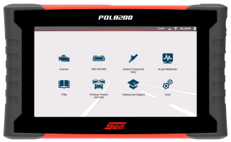
Features and Operations Overview
Contents
Most Popular
Software Activation / Registration
Installing the Battery & Powering Up
Important Information
Software Activation / Registration
Installing the Battery & Powering Up
Always dispose of the battery pack according to local regulations, which vary for different countries and regions. The battery pack, while non-hazardous waste, does contain recyclable materials. If shipping is required, ship the battery pack to a recycling facility in accordance with local, national, and international regulations.

-
Products bearing the WEEE logo are subject to European Union regulations
-
Contact your sales representative for details.
Connecting an External Monitor
|
Scanner (Common Icons) |
|||
|---|---|---|---|
|
Not all Icons are shown. Icons are not applicable to all tools. |
|||
|
|
Home - Return to Home screen, or open Quick- Access menu |
|
Accept - Accepts the highlighted selection |
|
|
Next / Forward |
|
Back / Last |
|
|
Save - Saves the active information to memory. |
|
Automatic ID - Automatically completes the identification process, once connected and make/year are entered. |
|
|
Single Selection (List) - Select / Deselect single item from list |
|
Multi-Selection (List) - Select / Deselect all items in a list |
|
|
Menu View - Toggle between categorized / |
|
|
|
|
Pause - Pauses active data collection. |
|
Start (Capture) - Resumes active data collection. |
|
|
Clear - Erases all the PID data in the buffer and restarts data collection. |
|
Custom Data List - Allows you to choose which PIDs display. |
|
|
Trigger - Allows you to set, arm, and clear PID triggers |
|
Change View - Toggle data display between list or graph. |
|
|
Zoom - Incrementally increases and decreases the scale of the data displayed. |
|
Lock - Locks PIDs to the top of the list. |
|
|
Step Forward - Allows forward movement in singular steps. |
|
Step Back - Allows backward movement in singular steps. |
|
|
Skip Forward - Allows forward movement in multiple steps. |
|
Skip Back - Allows backward movement in multiple steps. |
|
|
PID Alarm - Display visual indicators for two state PIDs |
|
Sort - Toggles the alpha order of a list. |
|
|
Data List Selector - Choose data list during functional test |
|
|
|
|
Diagnose - Opens Intelligent Diagnostics for the selected code. |
||
|
Code Scan |
|||
|
|
Refresh - Restarts the code scan |
|
System - Opens the main menu of the system selected |
|
Wi-Fi Icons |
|||
|
|
Indicates Wi-Fi is ON and Connected |
|
Indicates Wi-Fi is ON, Low Signal |
|
|
Wi-Fi On - Not Connected. |
|
Opens Wi-Fi Test screen |
|
Previous Vehicles and Data Icons |
|||
|
|
Delete - Deletes the selected item (menu dependent) |
|
View - Displays associated vehicle information and data file attachments |
|
|
Activate Vehicle - Starts the vehicle identification process, of the selected vehicle |
|
Edit - Modify vehicle information (VIN, odometer, etc) |
|
Software Updates (via Wi-Fi) |
|||
|
|
Down arrow - (displayed in upper status bar) indicates a software upgrade or update is occurring |
|
Check mark - (displayed in upper status bar) indicates when the update is ready to be installed. |
|
|
Exclamation mark - (displayed in upper status bar) indicates the update was interrupted (e.g. Wi-Fi connection was lost, or the Internet connection dropped out.) |
|
|


Fast-Track® Intelligent Diagnostics
 Wi-Fi Required
 Scope / Multimeter

Wi-Fi Required
 OBD-II/ EOBD

 Tools (Device Settings)
Wi-Fi Required
Wi-Fi Required
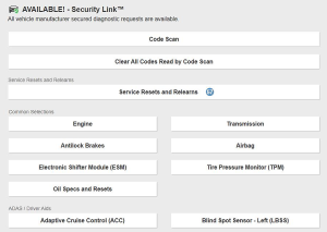
Security Link (Secure Gateway)
Videos - Configure Security Link (All Vehicles)
Wi-Fi Required
To protect vehicle communication networks from unauthorized access, OEM’s are implementing secure gateway modules that only allow authorized users to access certain diagnostic functions using an approved diagnostic tool.
To use Security Link you will need a compatible Snap-on diagnostic tool, and create an account as well as a Snap-on Technician Profile.
Getting Set Up (Fiat Chrysler Automobiles (FCA) 2018+ models)
| 1. | Connect your compatible diagnostic tool to Wi-Fi. |
| 2. | Select the Tools icon  from the Home screen. from the Home screen. |
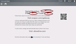
| 3. | Select Get Connected |
| 4. | Remember the following information from this screen: |
| ● | Serial Number |
| ● | Pin Code |
| ● | Activation Code |
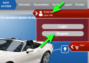
| 1. | Go to technicalinformation.fiat.com click the profile icon and then select Register. |
| 2. | Follow the screen prompts to register, starting with Accept the Terms and Conditions. |
| 3. | On the Technical Information Registration screen, enter your VAT-ID number. If you are a first time user then select NEW. |
| 4. | If needed, enter your company information as required including your VAT-ID (Value Added Tax Identification Number ). Attach (Attach File button) the required VAT documents as evidence of your VAT numbers and operation in the automotive sector. |
| 5. | Enter all registration information as required including your actual business location and billing address. Select Save as required and follow the screen prompts to continue. |
| 6. | Complete the security question section. |
| 7. | Select your Type of Business and then select Save to compete the registration. You will be sent a confirmation email with your "first time" user ID and password. |
| 8. | Open the email sent to the address you used to register and note the generated "first time" user ID and password. This email may take up to ten days to arrive. |
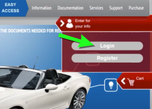
| 9. | After you receive your "first time" user ID and password, return to technicalinformation.fiat.com select Login (to be redirected to the FCA website). |
| 10. | On the FCA website, enter your "first time" user ID and password. |
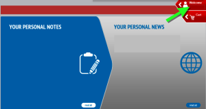
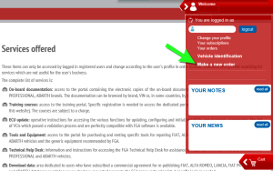
| 11. | On the main page click on the profile icon to access the menu. |
| 12. | Select "Make a new order", this allows you to setup your desired diagnostic tool access subscription. |
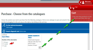
| 13. | Select the “Generic diagnostic tool” tab and then choose the subscription time period (e.g. 24 Hr, 1 mth, 1 yr. etc) and then drag/drop your selection into your shopping cart. |
| 14. | Confirm your purchase and make the required payment. |
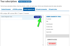
| 15. | After the payment has processed, you need to activate your subscription. Click on your profile icon (like before) to access the main menu, and select “Your subscriptions”, then select the “Generic diagnostic tool” tab and click the arrow on the “To activate” button to activate it. |
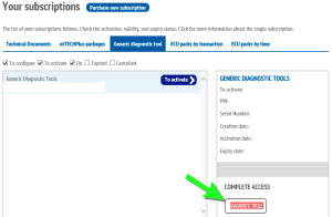
| 16. | Confirm your activation information on the screen, then click the "Diagnostic Tools" button. |
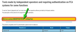
| 17. | To complete the activation, click the yellow button "Click here to activate...." on the activation screen. |
Your FCA account is now active.
If you do not have a Snap-on Technician Profile, you need to create one first, see Snap-on Technician Profile
| 1. | If you already have a Snap-on Technician Profile, log in and select the Device Management tab. |
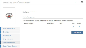
| 2. | (If you have not already linked your diagnostic tool to your Snap-on Technician Profile perform this step, if you have, then proceed to the next step.) Enter your Diagnostic Tool Pin Code and Serial Number from the Get Connected screen of your tool (See "Step 1 - Get your diagnostic tool information" at the beginning of these instructions). |
| 3. | Select the Security Link tab, then select Add Secure Credentials. |
| 4. | Enter your account username and password and select Save. |
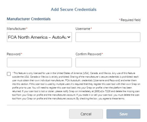
| 5. | Your diagnostic tool is now linked to your OEM account which allows you to connect and access the applicable secured gateways during scanner use. |
Downloading and Installing ShopStream Connect
| 1. | Using your PC or other applicable device, download ShopStream Connect from our website (it's free). Only use the applicable application for your market. |
https://eu.sun-workshopsolutions.com/en/products/shopstream_connect
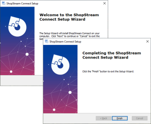
| 2. | If the SSC autorun installer does not automatically start the installation, double-click the SSC installation file ShopStreamConnect.exe, that downloaded onto your PC. |
| 3. | Follow the screen prompts in the Setup Wizard to complete the installation. |
Click on an image to expand, click again to reset size. Try it on the image below! Does not apply to all images/illustrations.
Connecting the USB Cable - PC to Tool
| 1. | Connect the USB-C cable to the PC and tool. |
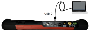
| 2. | Connect and use the AC power supply to power the tool, then turn on the tool. |
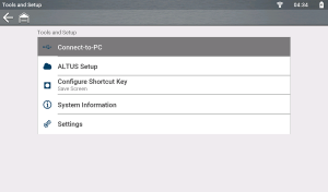
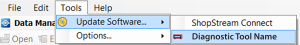
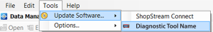
| 3. | From the Home screen on the diagnostic tool, select Tools, then select Connect-to-PC from the menu (typical screen shown below). The USB connection is automatic. |
| 4. | On the PC, start the ShopStream Connect application. |
Alternate Connection (micro SD)
If USB connection is not possible, the diagnostic tool micro SD card can be used to access files.
| 1. | With the diagnostic tool turned off, remove the micro SD card. |
| 2. | Use a micro SD card reader connected to your PC to access the files, using the SSC software. |
Starting SSC / Basic Navigation
Connect the diagnostic tool to your PC using a USB cable, or using an alternate method. See section PC to Tool USB Connection, and the applicable diagnostic tool instructions within that section.
In most instances, ShopStream Connect will automatically open on the PC when the tool establishes communication with the PC. See Tools Menu (Options) for information on using the Autostart function.
If needed, SSC can be started manually. Startup can vary depending on the Windows operating system. Typically SSC can be started from:
| ● | The ShopStream Connect icon  on the Windows desktop (automatically created during installation) on the Windows desktop (automatically created during installation) |
| – | Double-click ShopStream Connect icon. |
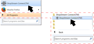
| ● | The Windows Start menu |
| – | Select ShopStream Connect directly from the Start Menu (Left Figure) programs if available, or |
| – | Select Start > All Programs > ShopStream Connect > ShopStream Connect (Right Figure) |
Basic Navigation / Menus
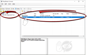
When the application opens, it should display the data stored on your diagnostic tool (if your tool is connected with the PC via USB).
If it does not open to display your data in the directory, select your applicable diagnostic tool from the file directory list.
ShopStream Connect uses the basic Windows interface to allow you to transfer files bi-directionally between your diagnostic tool and your PC.
When a diagnostic tool is connected to your PC using ShopStream Connect, a diagnostic tool folder is created on your PC named after the tool. This folder allows you to store and transfer files.
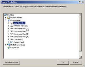
The location of the diagnostic tool “target destination” folders on your PC is defined during the installation of ShopStream Connect. The “target destination” folder names and location can be changed at anytime by choosing (from main menu) Tools > Options > Change ShopStream Data Path. Follow the onscreen instructions to create or rename your new “target destination” folder and/or location.
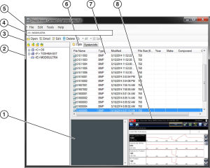
| 1. | Notes Window—allows you add notes to select data files. Select Save from the menu bar to save your notes. NOTE: Not all file types allow notes, the Notes window will be grayed out when a file type that does not support notes is highlighted. Some image files may display notes for reference purposes (the notes are grayed out and not editable). |
| 2. | File directory structure—displays the file directory structure of your PC in standard Windows format, and shows any connected diagnostic tools at the bottom of the data list. |
| 3. | Data Manager Toolbar—provides control icons that perform a variety of operations on data files. |
| 4. | File Path—displays the Windows file path. |
| 5. | Main Menu bar—contains File, Edit, Tools, and Help menus. |
| 6. | Tabs—provides access to data files and presets stored on the diagnostic tool or on the PC, and also allows viewing of software revision details of the diagnostic tool. |
| 7. | Main display —shows stored data files details. NOTE: The files listed are sortable (ascending/descending) by clicking on the column tab at the top (e.g. File Name, Type, etc.) Sort preferences are saved when the ShopStream Connect program is closed . |
| 8. | Preview—displays a sample of the file if the selected file is a image file. |
Main Menu Bar
File and Edit menus include standard Windows control options.
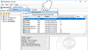
Update Software - Download updates and upgrades for your diagnostic tools and ShopStream Connect software.
| ● | Autostart |
| – | Allows you to set ShopStream Connect to automatically launch whenever a diagnostic tool in Connect-to-PC mode is connected to the PC, or a micro SC or CF card from a tool is recognized by your PC. |
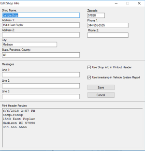
| ● | Edit Shop Info |
| – | Allows you to add your shop name and information to printed files and reports. |
| – | Check the “Use Shop Info in Printout Header” box to automatically include the header on printed files. |
| – | Check the “Use timestamp in Vehicle System Report” to enable the timestamp on the report. |
| ● | Change ShopStream Data Folder Path |
| – | Allows you to select a different target destination for the diagnostic tools folder on your PC. When a diagnostic tool is initially connected to a PC using ShopStream Connect, a diagnostic tool folder is created and named after the connected tool (e.g. PDL4200, etc). |
| – | Follow the onscreen instructions to select or create your new “target destination” folder and/or location. |
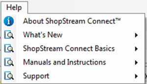
The Help menu includes SSC software information and links to help topics.
Using ShopStream Connect to Print Customized Vehicle Code Scan Reports
Adding Your Shop Information to the Report
| 1. | From SSC, select Tools > Options > Edit Shop Info. |
| 2. | A preview panel at the bottom of the box shows how the information will appear on a print out. |
| 3. | Check the “Use Shop Info in Printout Header” box to show the Shop Info in the printout. |
| 4. | Check the “Use timestamp in Vehicle System Report” box to show the time the vehicle was scanned in the printout. |
| 5. | When you are finished editing, select Save to save the information and close the dialog box. |
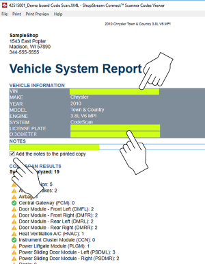
Editing the Report
After the report is generated, you can edit the VIN, License Plate, and Odometer fields, as well as add notes to the report, using SSC.
| 1. | From SSC, open the Vehicle System Report .XML file to be edited. |
| 2. | Click in the editable fields as shown to change the values or add notes. |
| 3. | Check the “Add the notes to the printed copy” box to show the notes in the printout. From SSC, select Tools > Options > Edit Shop Info. |
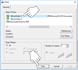
Printing the Report
| 1. | Open the applicable Vehicle System Report file from the list. |
| 2. | From the report viewer, selecting Print opens the Windows print dialog window. |
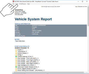
| 3. | Select your printer from the list, then select Print to print the report. |
Updating and Upgrading Software Using SSC
There are two diagnostic tool software update/upgrade methods:
| ● | Automatic Method — When a compatible Snap-on diagnostic tool is connected to a PC using ShopStream Connect (SSC), the SSC software will automatically check for updates/upgrades and provide installation instructions. Follow the screen prompts to accept, download and install the software. |
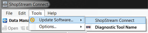
| ● | Manual Method — To manually check for software updates/upgrades from the SSC software, select Tools > Update Software, then select either ShopStream Connect or your diagnostic tool (diagnostic tool type - e.g. PDL 4200 --,, etc.) from the menu bar. |
The procedures described throughout this section use the manual method. The automatic method navigation procedures are the same, except the initial Tools menu selection is not needed as the program checks for updates/upgrades automatically.
Before You Start
| 1. | On your PC start the SSC software application. |
| 2. | Connect the AC power adapter to the diagnostic tool (if applicable). It is highly recommended to power the tool using the adapter during any update or upgrade procedure. |
| 3. | Connect your diagnostic tool to the PC. |
If you already have a version of ShopStream Connect installed, the automatic update feature will notify you when a new version is available, and guides you through the update procedure.
Upgrade / Update Descriptions (links):
| ● | Software Upgrade - a software upgrade is a new software version (contact your sales representative for purchase information). |
| ● | Software Update- a software update is a service release for installed software. These are available free of charge, and are provided as necessary to update installed software. When your diagnostic tool is connected to a PC using SSC, the SSC software will automatically check for updates, and if an update is available, it will provide installation instructions. Follow the screen prompts to accept, download and install the software. |
End User License Agreement
Before software installation at initial purchase, and before all subsequent software updates/upgrades installations End User License Agreement (EULA) acceptance is required.
To Accept: At the screen prompt click the checkbox on the left side of the window, and then select Agree and Continue. The software will be installed automatically.
The figure below represents a typical EULA acceptance agreement screen.
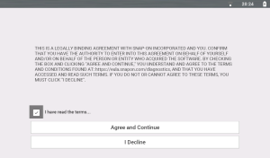
To Decline: At the screen prompt select I Decline. A confirmation message is displayed providing options to Go Back or Exit the software installation.
Updating Diagnostic Tool Software
Software Update - a software update is a service release for installed software. These are available free of charge, and are provided as necessary to update installed software. When your diagnostic tool is connected to a PC using SSC, the SSC software will automatically check for updates, and if an update is available, it will provide installation instructions. Follow the screen prompts to accept, download and install the software.
Typical Navigation = SSC Home Screen > Tools > Update Software > (diagnostic tool type - e.g. PDL 4200---,, etc.)
Selecting this option, checks the Snap-on Web server for available diagnostic tool software updates.
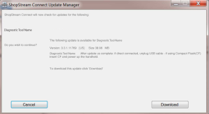
If updates are available, select Next to continue, then select Download and follow the on-screen instructions to complete the installation.
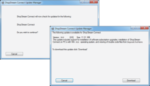
Upgrading Diagnostic Tool Software
Software Upgrade - a software upgrade is a new software version (contact your sales representative for purchase information).
Typical Navigation = SSC Home Screen > Tools > Update Software > (diagnostic tool type - e.g. PDL 4200---,, etc.)
Selecting this option, checks the Snap-on Web server for available diagnostic tool software upgrades.
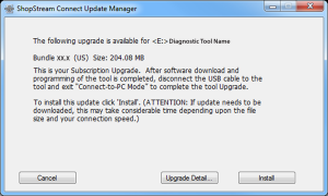
| ● | If the diagnostic tool is authorized to receive software upgrades and one is available, an upgrade window is displayed . |
| ● | If the diagnostic tool is authorized to receive software upgrades and already has the latest software, the following message will be displayed “ShopStream Connect did not find any updates”. |
| ● | If the diagnostic tool is not authorized to receive software upgrades, SSC software will automatically check the Snap-on web server for a Service Release update. If a Service Release update is available, an update window is displayed. Follow the screen prompts to install the Service Release update. |
| ● | If the Diagnostic Tool is not authorized to receive software upgrades, SSC software will automatically check the Snap-on web server for a Software Release update. If a Software Release update is available, an update window is displayed. Follow the screen prompts to install the Software Release update. |
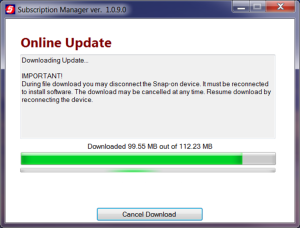
Read and follow the instructions displayed in the message box, then select Install to begin the download and installation.
The Online Update status window is displayed.
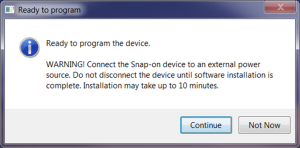
After the download is complete, the installation confirmation message is displayed. Select Continue to proceed with the software upgrade installation.
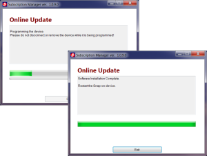
The Programming status window is displayed until programming is completed. Once programming is completed select Exit, then restart the diagnostic tool.
Do not disconnect or remove the diagnostic tool during programming.
Updating the ShopStream Connect (SSC) Software
Typical Navigation = SSC Home Screen > Tools > Update Software > ShopStream Connect
Selecting this option, checks the Snap-on Web server for available SSC software updates.
If updates are available, select Next to continue, then select Download and follow the on-screen instructions to continue the installation.
|
Item |
Description / Specification |
|
Touch Screen |
Capacitive Touch Panel |
|
Display |
10.1 inch diagonal, TFT Color LCD |
|
1024 x 600 resolution WSVGA |
|
|
Battery |
7.2 VDC 6000 mAh (43.2 Wh) Rechargeable lithium-ion battery pack |
|
Approximately 8hr @ 50% brightness run time |
|
|
Approximately 4.5 hour charge time |
|
|
Power Supply (included) |
Supply Rating; 15VDC, 1.6A 24W |
|
Power Supply(optional) |
When using USB-C power, the power supply must be USBC PD3.0 Compliant Charger Minimum 9V @ 24W |
|
DC Operating Voltage |
10 to 20VDC |
|
HDMI Output |
Micro-HDMI Type D (Micro) connector. Supports External LCD Monitor Resolutions: ☻ 800 x 600 60Hz ☻ 1024 x 600 60Hz |
|
Width |
12.2 in. (309 mm) |
|
Height |
7.5 in. (190 mm) |
|
Depth |
1.6 in. (40.7 mm) |
|
Weight (including battery): |
3.1 lb (1.4 kg) |
|
Operating Temperature Range (ambient) |
At 0 to 90% relative humidity (non-condensing) |
|
Storage Temperature (ambient) |
At 0 to 70% relative humidity (non-condensing) |
|
Operating Altitude |
Maximum 2000 m |
|
Environmental Conditions |
This product is intended for indoor use only |
|
This product is rated for Pollution Degree 2 (normal conditions) |
| Function | Range | Accuracy/Comments |
|---|---|---|
| Signal Measurement | Ch. 1— (yellow jack) Ch. 2— (green jack) | Each channel input is referenced to common ground (GND— black jack). |
| Sample Rate | For 50µS sweep 6 (MS/s) For 100µS sweep 3 (MS/s) For all other sweeps 1.5 (MS/s) | Continuous sampling, (MS/s) = mega samples per second |
| Band Width | 3 MHz | 3 db point @ 3 MHz |
| Zoom In |
Supported for 1ms sweep and above |
Available levels are determined by sweep setting (Max. + X15) |
| Input Impedance | 10 MΩ @ DC 4 kΩ @ 3 MHz | Channel 1 and 2 |
|
Category Rating |
CAT I |
|
| VDC (Full Scale) | 100mV–400V | Do not measure greater than 75VDC |
| VAC (Full Scale) | 100mV–400V | Do not measure greater than 50 VAC (rms). |
| Low Amp Probe | 20A scale (100mV/Amp) 40A scale (10mV/Amp) 60A scale (10mV/Amp) | Connect the positive (+) Amp Probe lead to the yellow jack on the diagnostic tool for values on Ch.1, or to the green jack for values on Ch. 2. Connect the negative (–) lead to GND (black jack)1*. |
|
1*. Do not use the Low Amp Probe to measure current on conductors at a potential greater than 46VAC peak or 70VDC. |
||
| Function | Range | Accuracy/Comments |
|---|---|---|
| Signal Measurement | Ch. 1— (yellow jack) Ch. 2— (green jack) | Each channel input is referenced to common ground (GND— black jack). |
| Sample Rate | 1.5 MSPS | Continuous sampling, (MS/s) = mega samples per second |
| Band Width | 3 MHz | 3 db point @ 3 MHz |
| Input Impedance | 10 MΩ @ DC 4 kΩ @ 3 MHz | Channel 1 and 2 |
|
Category Rating |
CAT I |
|
| VDC (Full Scale) | 75VDC | Do not measure greater than 75VDC |
| VAC (Full Scale) | 50VAC | Do not measure greater than 50 VAC (rms). |
| Low Amp Probe | 20A scale (100mV/Amp) 40A scale (10mV/Amp) 60A scale (10mV/Amp) | Connect the positive (+) Amp Probe lead to the yellow jack on the diagnostic tool for values on Ch.1, or to the green jack for values on Ch. 2. Connect the negative (–) lead to GND (black jack)1*. |
|
1*. Do not use the Low Amp Probe to measure current on conductors at a potential greater than 46VAC peak or 70VDC. |
||
| Function | Range | Accuracy/Comments |
|---|---|---|
| Signal Measurement | Ch. 1— (yellow jack) | Input is referenced to common ground (GND— (black jack) |
| VDC (Full Scale) | 75VDC | Do not measure greater than 75VDC |
| VAC (Full Scale) | 50VAC | Do not measure greater than 50VAC (rms) |
| Signal Measurement Input Impedance | 10 MΩ | |
|
Category Rating |
CAT I |
|
| Ohm Measurement Diode Test Continuity Test | Ch. 1— (yellow jack (–)) Ch. 2— (green jack (+)) | |
| Ohms | 40 Ω—4 MΩ | Fixed scales or auto ranging |
| Glitch Capture | Approximately 50 µS | |
| Diode test | 2V scale |
| Item | Description / Specification |
| Communications | Wireless Bluetooth® 2.1 Technology |
| Operating Range | Approx. 50 feet (15.24 m) |
| USB Power | Max. 5V @ 0.9A |
| DC Operating Power | Scan Module Model EESM3060B: 8-32 VDC, Max. 10W,Scan Module Model EESM317A: 8-32 VDC, Max. 6.5W |
| Width | 1.87 in. (47.5mm) |
| Height | Ch. 0.95 in. (24.2mm) |
| Depth | 4 in. (101.7mm) |
| Weight | A0.22 lb (100 g) |
| Operating Temperature Range (ambient) | At 0 to 80% relative humidity (S9 and S10 were done in 80% RH environment) |
| Storage Temperature (ambient) | At 0 to 70% relative humidity (non-condensing) –4 to 140°F (–20 to 60°C) |
| Operating Altitude | This product is intended for indoor use only |
| Environmental Conditions | This product is rated for Pollution Degree 2 (normal conditions) |
| Certifications | Scan Module Model EESM317A
Conforms to UL STD UL 201, 62368-1 Certified to CSA STD C22.2# 62368-1 |

For your safety and the safety of others, before you operate this device follow this link to read and understand the Important Safety Information.
Website – snapon.com/diagnostics/uk
Phone – +44 (0) 845 6066512
E-Mail – diagukps@snapon.com
ShopStream Connect™ – https://www.snapon.com/EN/UK/Diagnostics/Diagnostics/Platforms/ShopStream-Connect
Snap-on® Cloud – www.altusdrive.com
Use of Software is governed by the terms and conditions of the End User License Agreement. The diagnostic tool should not be initially operated until the End User License Agreement is read. Use of the device acknowledges your acceptance of the End User License Agreement. The Snap-on Incorporated Software End User License Agreement may be provided with the diagnostic tool, and is available at: https://eula.snapon.com/diagnostics
For customer and end-user access and convenience, Snap-on is providing the End User License Agreements (link above) applicable to the Snap-on Diagnostics software and platforms. These agreements or an earlier one you agreed to was either provided as hard copy or resident within the diagnostics platform software.
Snap-on, Sun, Fast-Track, SureTrack, ShopStream, and ShopKey Pro are trademarks registered in the United States and other countries of Snap‑on Incorporated. The aforementioned trademarks are not an inclusive list of all the registered trademarks that may be used within this content, those trademarks are a partial list of all the trademarks registered in the United States and other countries of Snap‑on Incorporated. All other marks are trademarks or registered trademarks of their respective holders.
The Bluetooth word mark and logos are registered trademarks owned by :Bluetooth SIG, Inc. and any use of such marks by Snap-on Incorporated is under license.
All pictures and illustrations shown are for reference purposes only. All information, specifications and illustrations in this manual are based on the latest information available at the time of printing and are subject to change without notice. While the authors have taken due care in the preparation of this manual, nothing contained herein:
-
Modifies or alters in any way the standard terms and conditions of the purchase, lease, or rental agreement under the terms of which the equipment to which this manual relates was acquired.
-
Increases in any way the liability to the customer or to third parties.
Snap‑on® reserves the right to make changes at any time without notice.
For a listing of Snap-on products that are protected by patents in the United States and elsewhere, visit: https://patents.snapon.com