Automotive Data Cable / Connections
Automotive Ethernet can be thought of, as the physical networking architecture used to allow multiple vehicle controllers and components to communicate. Ethernet can transport data 100 times faster than CAN and is better suited for the needs of modern safety systems. Just as CAN Bus communications are monitored via the OBD-II diagnostic link connector, Ethernet Bus communications can be monitored in the same way.
Ethernet equipped vehicles use the standard 16 pin OBD-II diagnostic link connector for diagnostic tool connection, however the diagnostic tool and/or data cable must be designed to support Ethernet communication.
If your diagnostic tool and data cable are compatible with Ethernet communication, It will connect to the vehicle automatically.
If your diagnostic tool and/or data cable are not compatible with Ethernet communication, when you try to connect you may be prompted to connect a special data cable. For example, "Use the DA-4EA Ethernet adapter cable. This vehicle is equipped with and Ethernet communications system. Please see your sales representative for more information."
In order to communicate via Ethernet, follow the prompts on the diagnostic tool to use the data cable marked “DA-4E” or “DA-4EA” . Substituting a different data cable may result in no or an erroneous communication condition.
Snap-on supports Ethernet communication for select Jaguar, Land Rover and Volvo models.
Only use the supplied data cable, and/or original equipment accessory cables with your diagnostic tool. Total data cable length must not exceed 114.17 inches (2.9 meters).
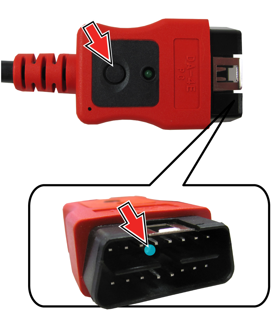
The diagnostic tool will automatically turn on when the Data Cable is connected to a vehicle that has 12VDC at the data link connector (DLC). An LED indicator on the DLC end of the data cable illuminates when power is being supplied. If the LED fails to illuminate, check the data cable connection and then the DLC power circuit.
| 1. | For OBD-II/EOBD compliant vehicles, connect the DA-4E data cable (26 pin end) to the diagnostic tool. Connect the cable with the arrow facing up (display side). |
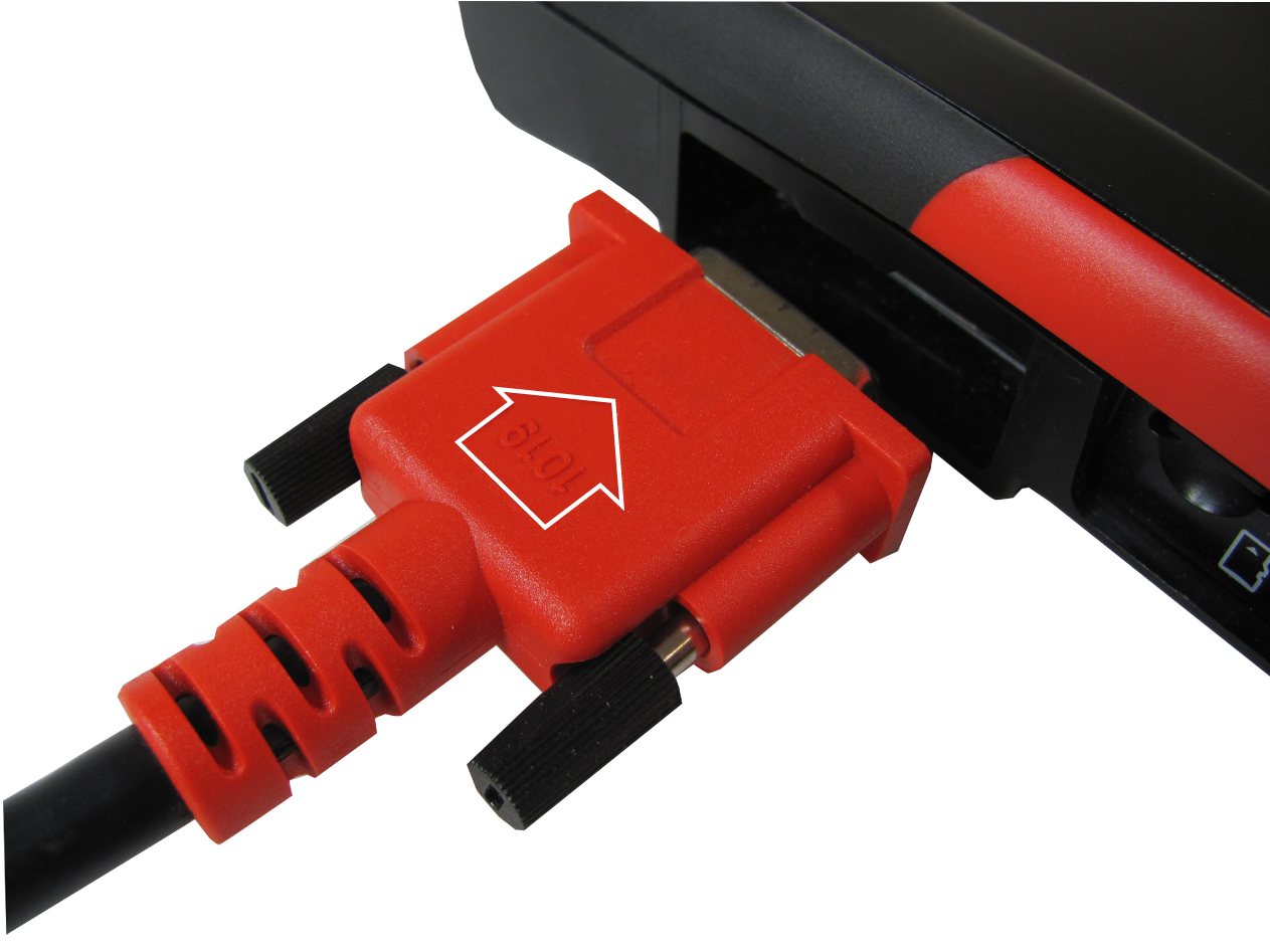
1Arrow highlighted for illustration purposes only.
The supplied data cable, includes an LED flashlight on the vehicle DLC connector end. The LED flashlight is powered by the diagnostic tool battery, and is useful when locating the vehicle DLC.
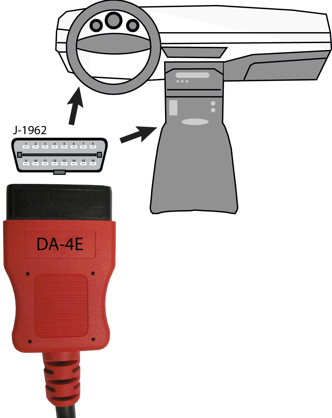
| 2. | Connect the 16‑pin (J-1962) end of DA-4E cable to the vehicle DLC. |
3
During vehicle identification, on-screen cable connection instructions may be provided along with the location of the DLC.