As the information and tests provided within the Guided Component Test function is vehicle specific, the vehicle must first be identified in order to retrieve the correct data.
The vehicle identification process is the same as the process used for the Scanner function. Once the vehicle is identified, a list of Systems is displayed.
Depending on the vehicle and component selected, different options and sub-menus may be displayed.
Information and tests may vary, see the following topics (dropdowns) for additional information:
| 1. | Select a system from the list. |
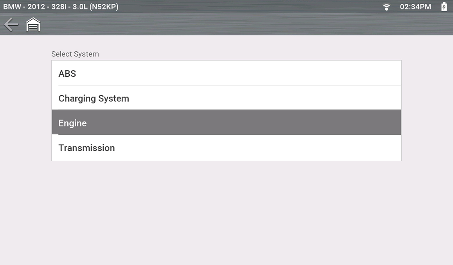
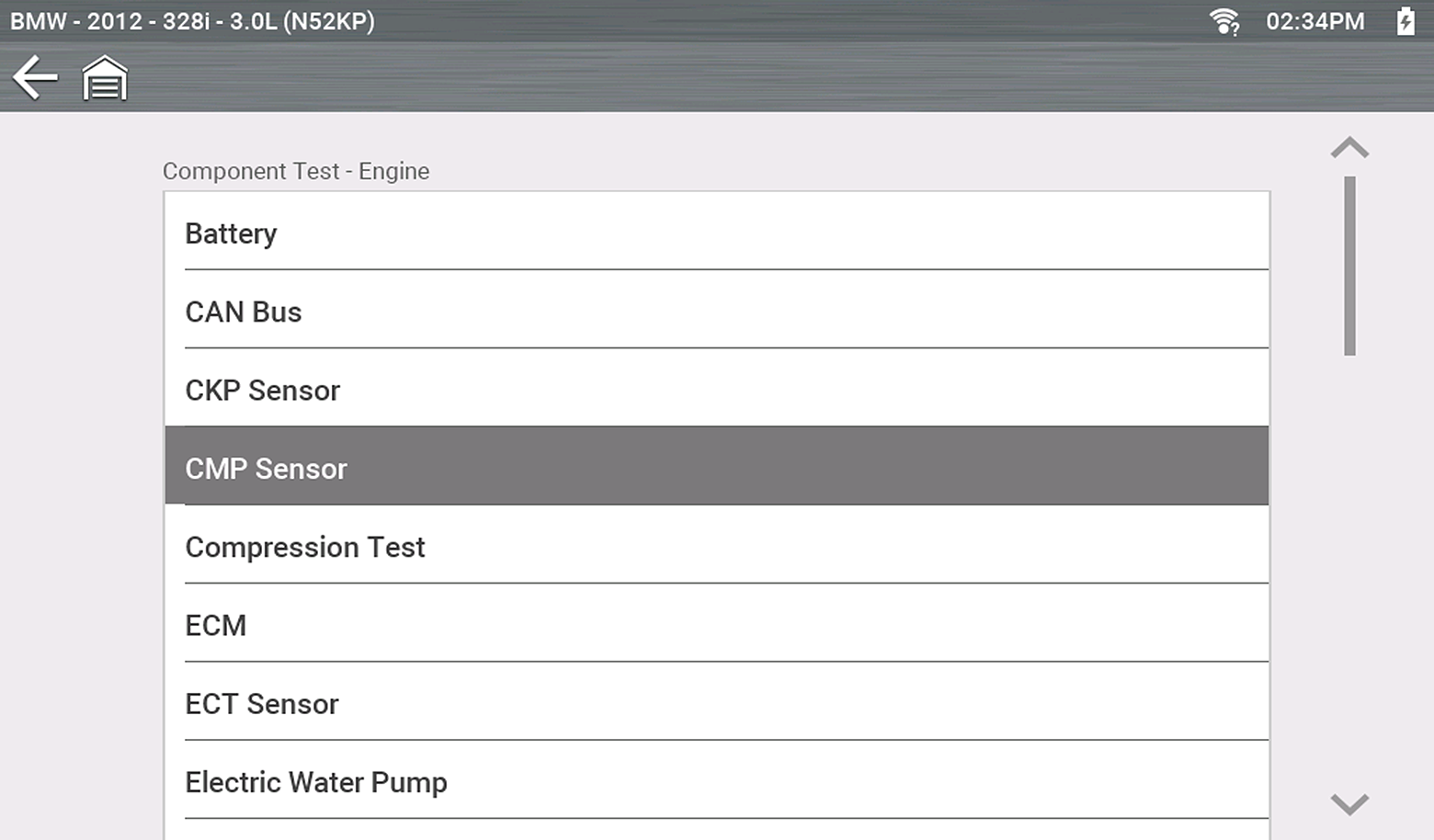
A list of Components (and/or sub systems) is displayed.
| 2. | Select a Component to continue. |
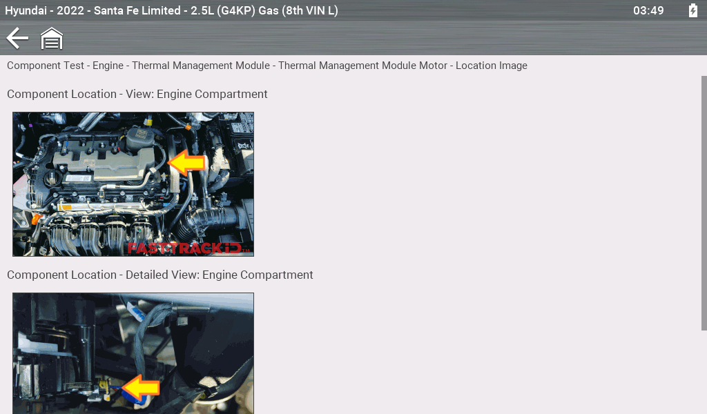
For select vehicles, photo images of the selected component's location may be available.
| 1. | Example: After selecting a component such as "Thermal Management Module" |
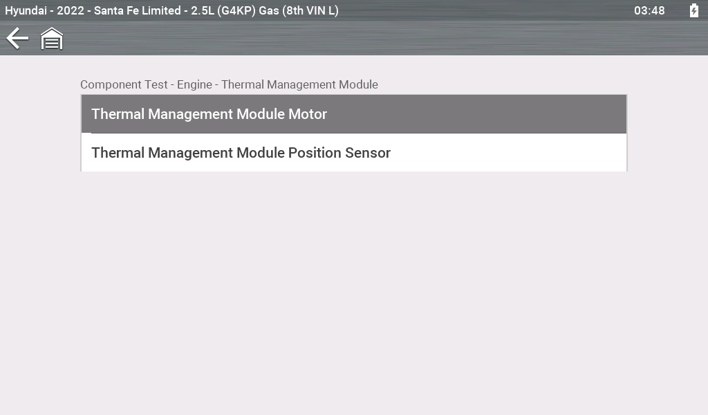
| 2. | Select Location Image. |
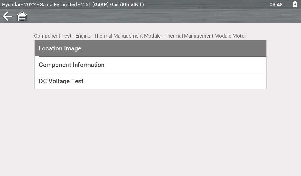
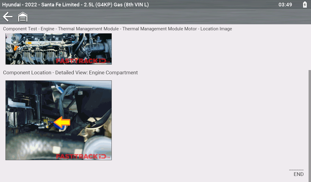
If multiple images are displayed, the first image typically indicates the general location and then more location details in the subsequent images.
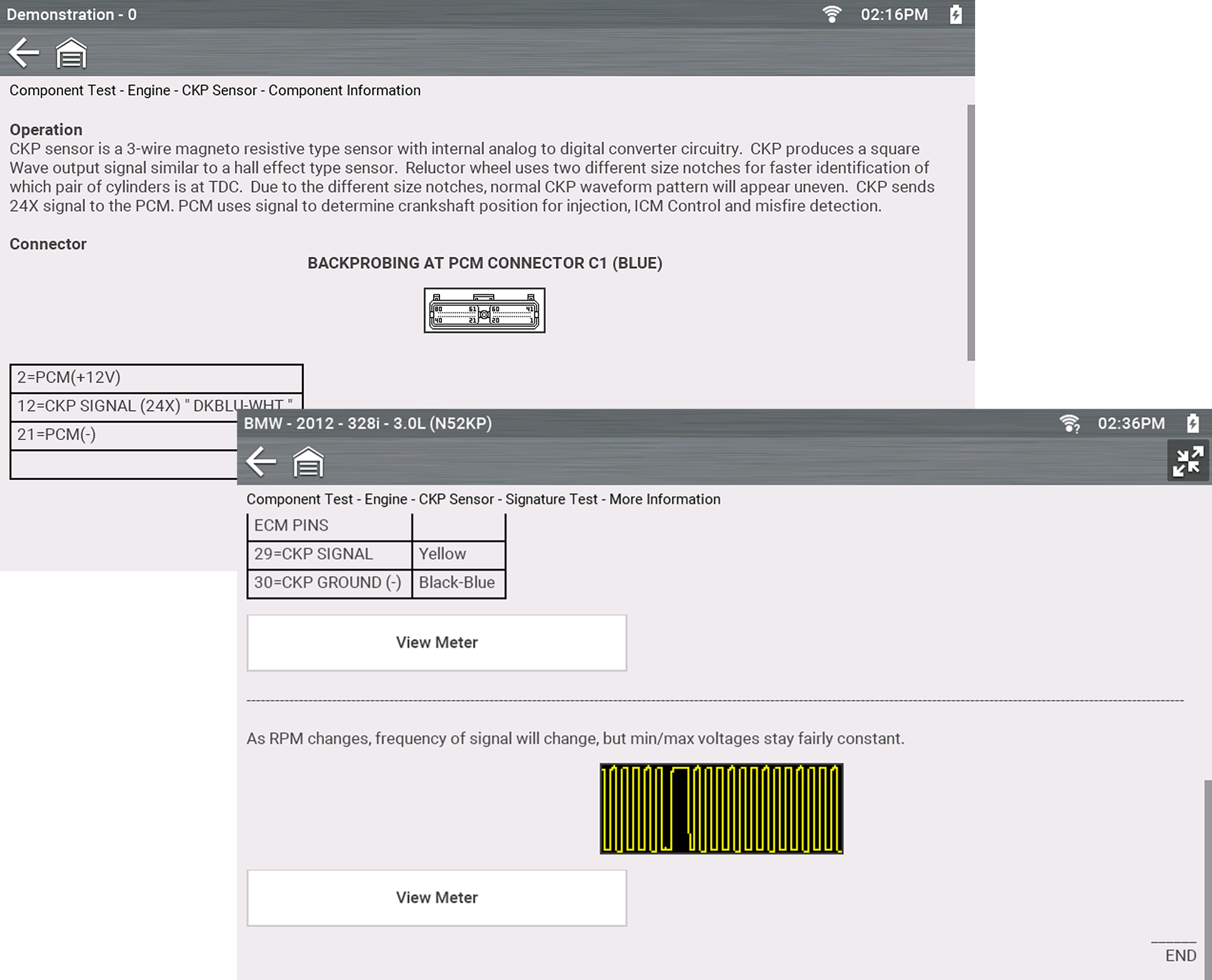
Component Information provides (if available) specific operational information on the selected component, and may also include electrical connector and pin location and function details
| 1. | Select a component. |
| 2. | Select Component Information from the Component Test menu. |
An additional selection may be required for some components (e.g. selecting front or rear for an oxygen sensor (O2S).
Component Information is displayed.
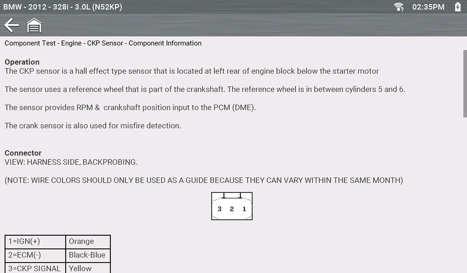
Screens are divided into sections to quickly guide you to the correct information (available sections and information will vary):
| ● | Operation—provides a general description of component operation. |
| ● | Tech note—provides component related tips (e.g. common failures or faults), additional information may include OEM service updates and recall information. |
| ● | Connector—displays illustrated electrical connectors and socket/pin identification. |
| ● | Location—provides component locations, testing tips, and alternate testing locations if available. |
Use the scroll bar to view additional information.
| 3. | Select Back on the Toolbar, or press the N/X button, to return to the component menu. |
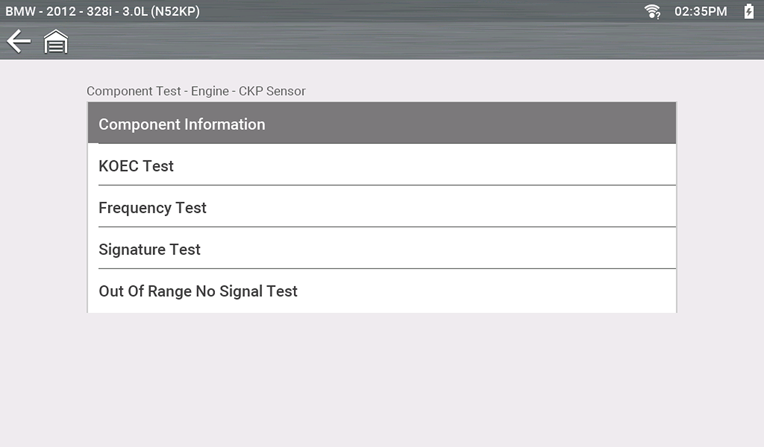
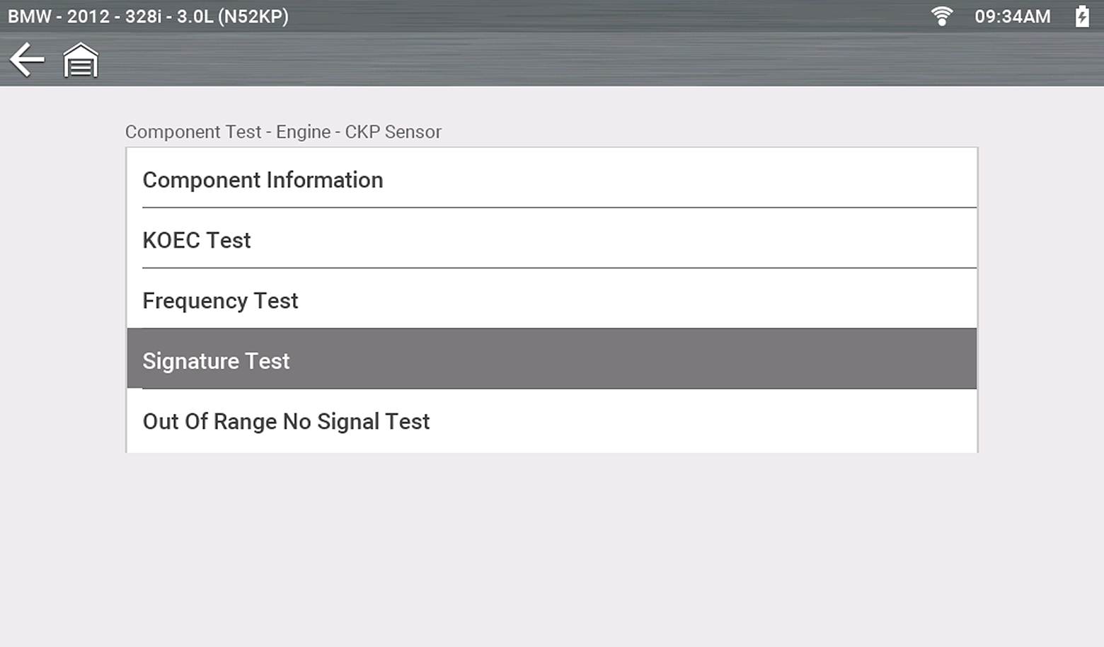
Tests provides (if available) specific instructions to help you perform tests on components. Selecting a component test opens a preconfigured meter to start the test, and may also provide connection instructions, specifications and testing tips.
| 1. | Select a component. |
| 2. | Select a Test from the Component Test menu. |
The component test menu lists all of the tests available for the selected component. Choices vary by the type of component, as well as the make, model, and year of the vehicle.
An additional selection may be required for some Component Tests
(e.g. selecting front or rear for an oxygen sensor).
The test connection information screen displays.
Use the scrollbar to display hidden information.
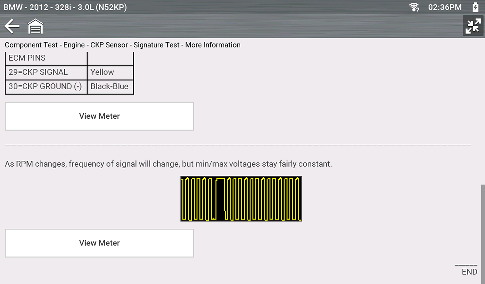
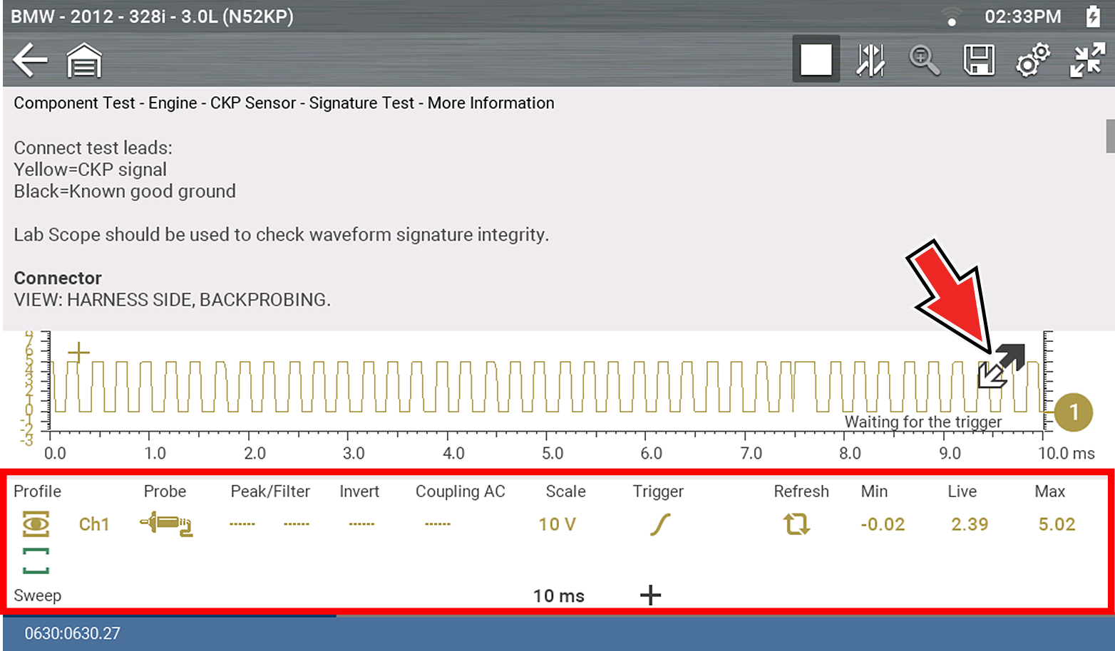
| 3. | Select View Meter to display the meter display and to perform the test. |
| 4. | Use the Expand/Collapse icon to toggle through split and full screen views and to display the control panel. |
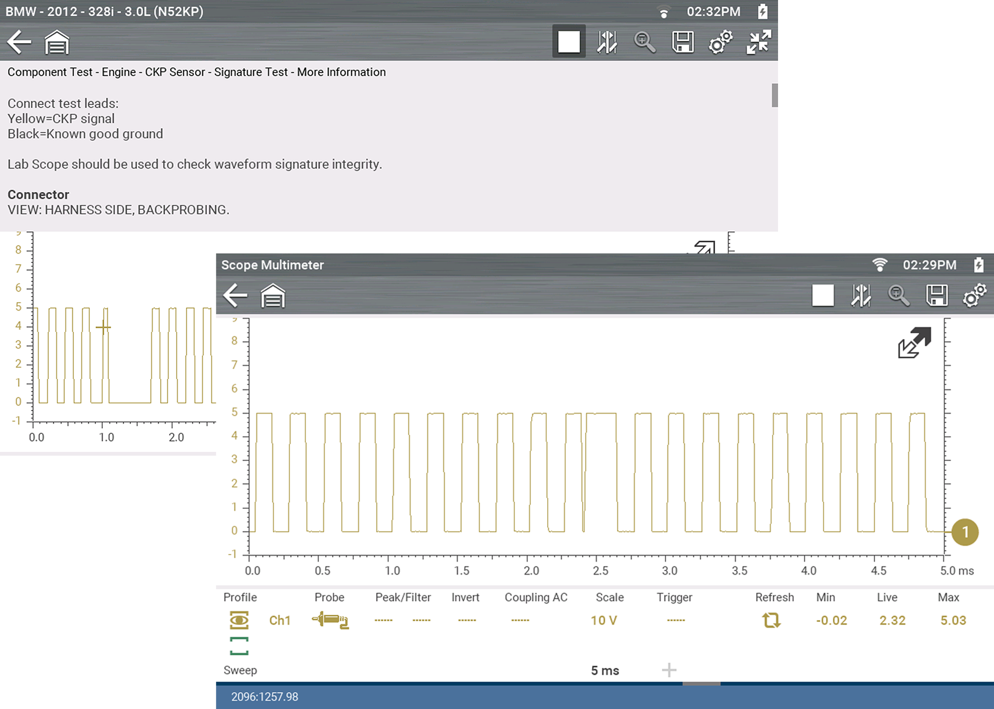
Some tests (e.g. signature integrity tests) may include waveforms examples within the information panel. These waveform examples allow you to compare your test results for quick diagnosis .
The test meter is preconfigured, for most of the component tests. However, if the need to change channel settings is needed, adjustments can be made by using the Control Panel. To access the Control Panel, use the Expand/Collapse icon to toggle the view.
Save and Stop control icon operation and data review procedures are the same as used for the Scope/Multimeter function.


