Introduction
To meet the demands of Drive-by-Wire systems and Advanced Driver Assistance Systems (ADAS), vehicle manufacturers, in association with electronic component manufacturers, investigated possible solutions for high-speed data transfer. In the previous article we looked at CAN (Controller Area Network) Bus communication, however, with safety-critical Drive-by-Wire systems, a higher data transfer rate and improved error detection is required.
Vehicle manufacturers; Volkswagen, BMW, Daimler and General Motors became core members of the FlexRay consortium.
Physical Layer
FlexRay is similar to CAN Bus as the data is transmitted over two twisted wires. These act to reduce the effects of external interference on the differential voltage between both wires. Data transfer speeds can be up to 10 times faster than CAN bus, operating at speeds up to 1 Mbit per second. Although the normal data transfer speed for CAN is 500 Kbits per second, it has the capability to transmit at speeds of 1 Mbit per second.
FlexRay can support network redundancy, or dual channels. This ensures greater fault tolerance as well as increased bandwidth for additional data transfer. However, this additional network is rarely implemented.

Signal Conditioning
To match the impedance of the network cabling, a terminating resistance of 90 to 110 Ω within the modules at either end of the network is required. This ensures signal reflections are reduced, which is an issue with such high data transfer speeds.
Bus Access
CAN bus messages are subject to arbitration to ensure messages of higher priority have access to the network first. FlexRay supports both Event triggered messaging and Deterministic messaging which allows for high data rates and guarantees message delivery when required. Each node or module has a predetermined time slot to transmit its data. This is referred to as Time Division Multiple Access or TDMA.
For sporadic messaging (event driven) TDMA is not optimal, so Flexible Time Division Multiple Access or FTDMA is used.
FlexRay Voltages
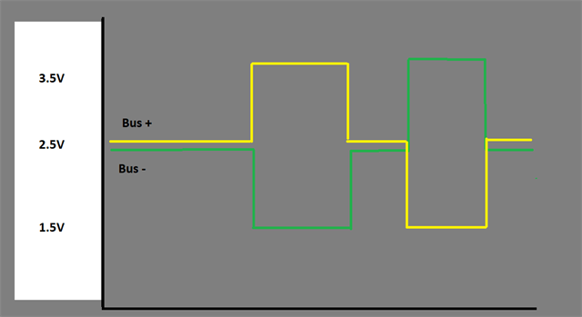
FlexRay Bus voltage is similar to CAN Bus. With the Bus idle or in a recessive state, the voltage present on both wires, Bus (+) and Bus (-), is 2.5 volts.
Approximate voltage levels
When a logic bit of 1 is required the Bus (+) voltage increases to 3.1 volts and the Bus (-) voltage reduces to 1.9V. This creates a differential voltage of +1.2 volts.
When a logic bit of 0 is required the Bus (+) voltage reduces to 1.9 volts and the Bus (-) voltage increases to 3.1 volts. This creates a differential voltage of -1.2 volts.
Two Channel Network Voltage
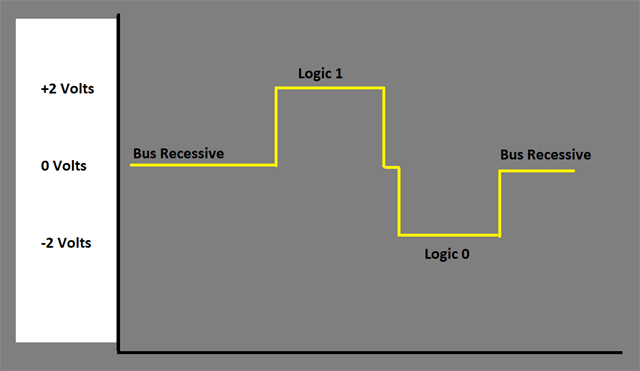
Differential Voltage
BMW X5 Vertical Dynamics Control Module
The E70 BMW X5 was the first production vehicle to have a FlexRay network fitted. It is implemented for the Vertical Dynamics Control module, which controls the suspension height for each individual suspension strut.
The network is configured in a Star Bus. This ensures the system can still operate if a satellite unit fails. Also, it is an advantageous setup when long lengths of wiring are required, as normal electrical interference will only affect one leg of the network due to this configuration. A satellite unit is located in each corner of the vehicle.
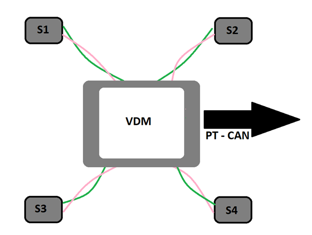
- VDM – Vehicle Dynamics Control Module
- S1 – Satellite sensor Left Front
- S2 – Satellite sensor Right Front
- S3 – Satellite sensor Left Rear
- S4 – Satellite sensor Right Rear
- PT CAN – Powertrain CAN Bus
A terminating resistor of 90 – 110 Ohms is fitted in each of the satellite units.
Waveforms
Due to the incredibly high data transfer speed of FlexRay, in depth waveform analysis is difficult. However the oscilloscope can be used to validate that a signal is present on the network and to test for an open or short with in the circuit.
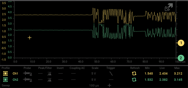
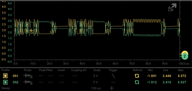
The waveform below shows a trace captured from a FlexRay system. The zero lines are set up to show the transition between a Logic 1 and Logic 0 bit due to the voltage switch for Bus (+) and Bus (-).
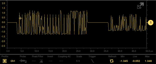
The waveform below shows the differential voltage between Bus (+) and Bus (-). This is observed using a single channel test with Channel 1 connected to Bus (+) and the oscilloscope ground connected to Bus (-).
The waveform below shows Bus (+) and Bus (-) separated to show the mirror image of both traces.