The Brushless Direct Current (BLDC) motor
The rise in demand for ‘high-tech’ vehicles has challenged engineers to rethink and create more sophisticated internal systems that promote efficiency. The humble motor is a great example of this, with many vehicle manufacturers now using brushless direct current (DC) motors in automotive applications.
The brushless motor has many advantages when compared to conventional ‘brushed motors’:
- It produces less noise since the interaction between the brushes and commutator is no longer a factor
- No electrical arcing takes place
- There is a greater service life. In theory, this motor should last the lifetime of the vehicle
While more efficient, the commutation control of the brushless motor is more complex.
Brushed Motor Operation
A conventional ‘brushed motor’ uses two brushes (one positive and one negative) to allow current to flow to the motor’s armature. The reason for this is that a magnetic field must be set up within the armature winding which opposes the magnetic field generated by the permanent magnets. These are attached to the motor casing (yoke). The opposing magnetic fields will cause the armature to rotate due to the repulsion/attraction of the magnetic field.
The polarity of the current flow through the armature is ‘switched’ by the commutator segments. These segments provide the link between the brushes and the armature. This allows for constant and smooth rotation of the armature while the current is flowing through the motor.
Understanding the Brushed Motor Waveform
Figure 1 shows the current flow through a “brushed” fuel pump from a Ford Focus. The commutator has eight segments with each segment having a slightly different current profile. By identifying one segment, we can use the cursors to calculate the time for one revolution of the pump. In this example, the pump speed is 8.61ms for one revolution. This equates to almost 7,000 RPM. The calculation for this means that there are 60,000ms in one minute, equating to 60,000 / 8.61 = 6,969 RPM.
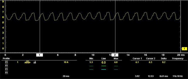
Figure 1: Brushed Motor Waveform
Brushless DC Motor Operation
A blockage in the fuel system will result in lower speed and higher current flow, whereas a leak within the fuel system will result in higher speed operation and lower current flow. Occasionally a vehicle may present with low fuel pressure with no visible leak. An area that should be investigated is the pipe from the fuel pump to the top of the tank unit. A leak here will result in a fuel leakage within the fuel tank.
Previously this was achieved by using digital hall-effect sensors on the rotating member of the motor. This resulted in additional hardware and cost. Another method is for the control module to motor the back electro-motive force (EMF) in the un-energized winding.
Figure 2 shows an illustration of a fuel pump control module. Note the colored winding, the yellow, green and blue all respond differently, which is explained further below
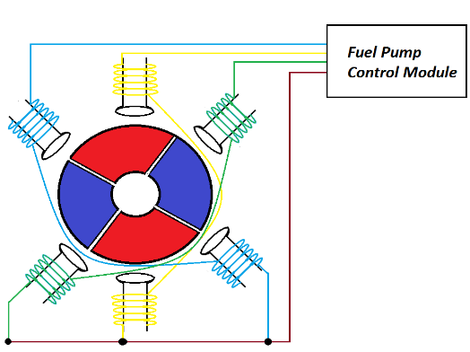
Figure 2: Fuel Pump Control Module
It must be noted that whichever winding is un-energized will have half the applied voltage present during operation. This is due to the connection point being between windings. Kirchhoff’s law states that the sum of the volt drops in a series circuit is equal to the applied voltage. This can be seen in figure 3.
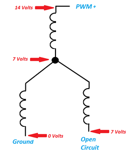
Figure 3: Voltage drop in a series circuit
This table demonstrates the module control of each phase during operation. At any one time, a phase is on (PWM), connected to ground or uncoupled from the circuit. Figure 4 helps show what that should visually look like.
| YELLOW TRACE |
GREEN TRACE |
BLUE TRACE |
| OFF |
GROUND |
PWM |
| PWM |
GROUND |
OFF |
| PWM |
OFF |
GROUND |
| OFF |
PWM |
GROUND |
| GROUND |
PWM |
OFF |
| GROUND |
OFF |
PWM |
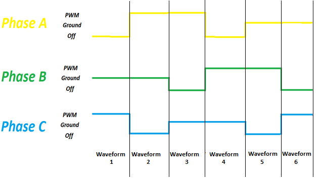
Figure 4: A visual of the 'on', 'ground' or 'uncoupled' phases
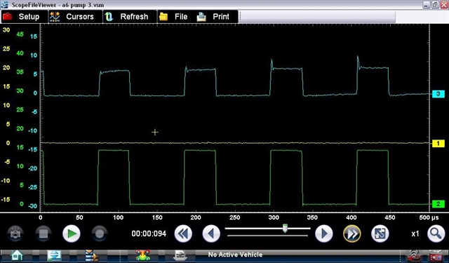
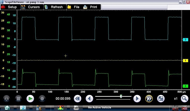
The oscilloscope waveforms below are from a vehicle and can be used to identify each phase’s control during normal operation. These images match the table above.
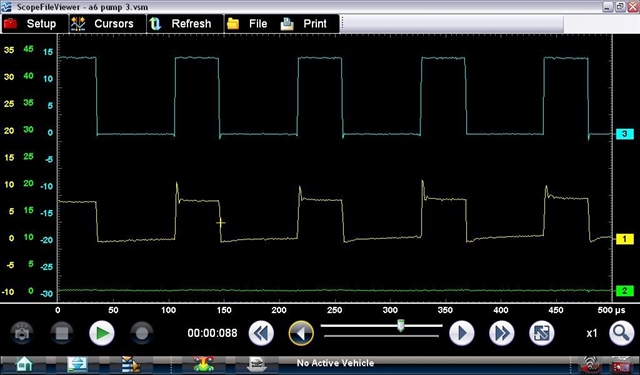
Waveform 1
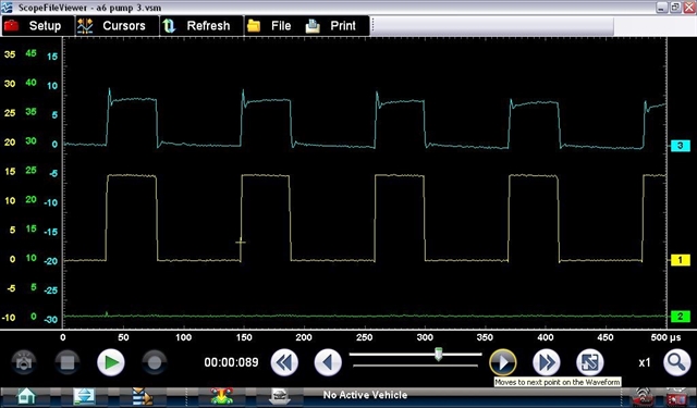
Waveform 2
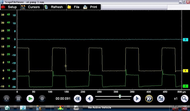
Waveform 3
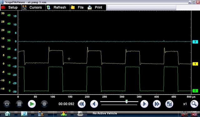
Waveform 4
Waveform 5
Waveform 6
Guided Component Training
If you have a compatible Snap-on platform with Guided Component Tests, be sure to take a look at the Training Class. (See Figure 5.)
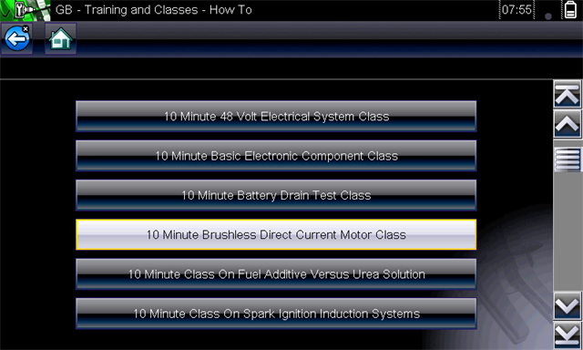
Figure 5: Training