Local Interconnection (LIN) Bus is a low speed cost effective alternative to CAN bus. LIN gets its name from being a ‘local’ sub-system. Data Transfer speeds can be up to 20 kBits/second. It is designed for sensor/actuator level.
Data Transfer Speed:
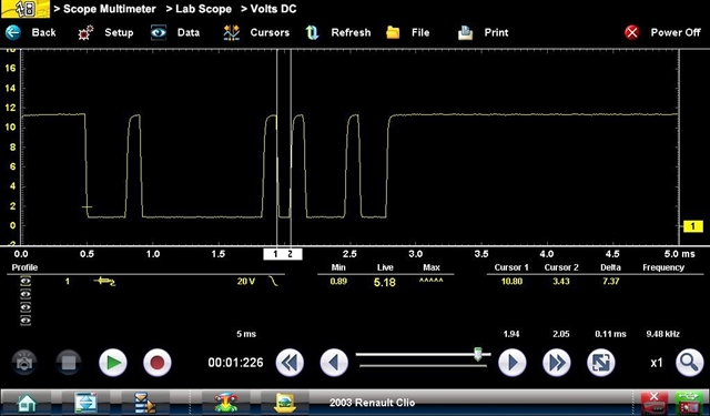
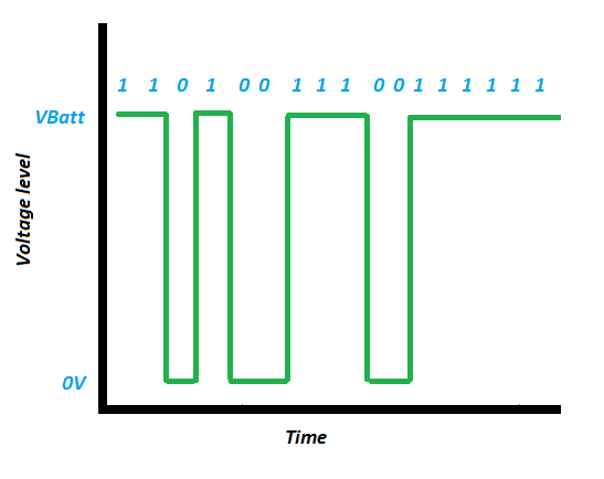
The waveform below shows a typical LIN trace, the time for the transmission of one bit is 0.11ms, this equates to a data transfer speed of 9480 bits per second (approximately 10 kBits/second).
Network Topology:
The bus can contain up to 16 modules or subscribers. One master (module) and fifteen slaves (intelligent components). LIN is a linear bus topology, with communication over a single wire.
The illustration below shows a basic network topology:
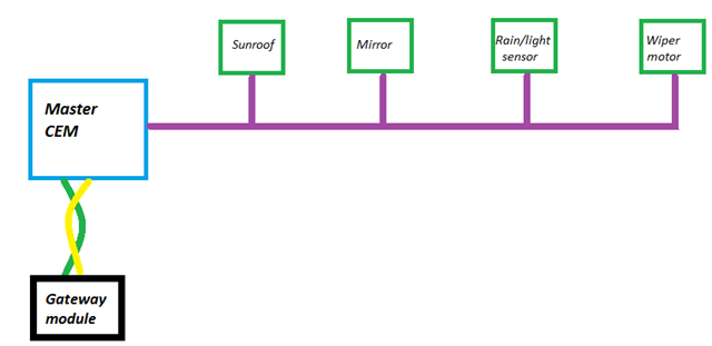
The Central Electronics Module (CEM) is the master module and communicates with the gateway module using Controller Area Network (CAN) bus. Each of the LIN components is a sensor or actuator, with the ability to transmit and receive a LIN message. The master module is responsible for controlling the timing of the message data packet.
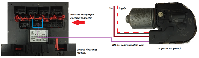
The image above shows a CEM and front wiper motor. The purple wire is the LIN bus wire and is used to control the speed and intermittent delay for the wipers.
Message Structure:
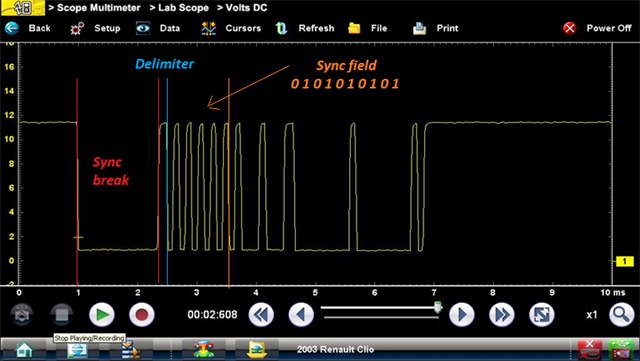
The waveform below shows a LIN message with the defined message structure. The “Sync Break” is used to signal the beginning of the message. The delimiter indicates the completion of the Sync break and serves to show the LIN wire isn’t shorted to ground. The Sync field is to ensure the timing of the message is set prior to the data field being transmitted. This is not required for CAN bus as each module on the network has its own time clock for message timing.
The message is transmitted by manipulating the voltage on the LIN data circuit.
1 = Recessive bit.
2 = Dominant bit.
For accuracy of data transfer the following conditions must be met:
For a recessive bit, the LIN voltage must be greater than 80% of the battery voltage.
For a dominant bit, the LIN voltage must be less than 20% of the battery voltage.
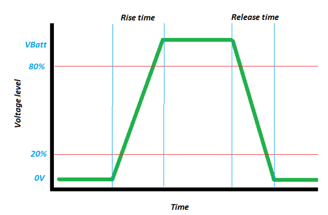
The slew rate or transition time between a high bit and a low bit is critical too for data transfer.
Vehicle charging systems:
One particular system which has utilised LIN bus communication is the vehicle charging system. The diagram below shows a conventional charging system layout fitted to an older vehicle.
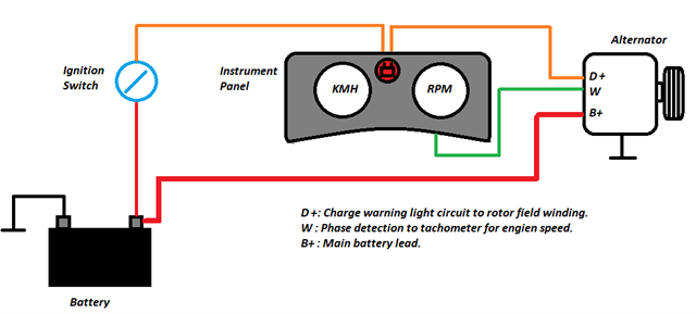
The D+ terminal is used as an exciter current for the rotor field winding. The rotor field winding is wired in series with the charge warning light. The W terminal was used for measuring engine speed by tapping off a stator phase.
A layout of a modern system using LIN bus is shown below:
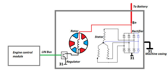
The internals of the alternator are fundamentally the same:
- Rotor poles.
- Rotor field winding.
- Stator.
- Rectifier (used to convert Alternating Current to Direct Current).
The exception being the Engine Control Module uses the LIN bus to control a transistor which varies the current flow through the rotor field winding to control the output voltage of the alternator.
Part 2 of this article will address CAN Bus communication networks.
.
Date posted: 16 December 2020