The mechanical operation of a fuel injector on a spark ignition engine can be assessed with an oscilloscope using a two-channel test.
This test is only applicable to low pressure fuel injectors due to the construction and operation of the injector.
High-pressure injectors fitted to direct injection spark ignition and common rail compression ignition engines use hydraulic imbalance to open the injector, so this test is not suitable for these applications.
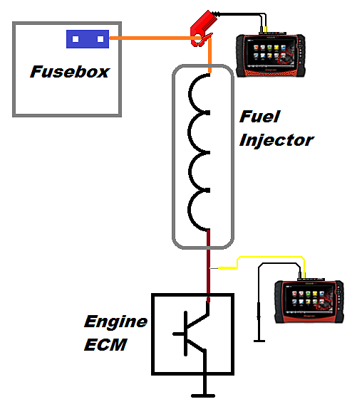
In the diagram below the fuel injector is supplied with a hard live from a fuse. When the injector is to be actuated, the engine control module connects the negative side of the winding to ground through a transistor.
Current will flow through the injector winding until the path to ground is interrupted. This duration or period is referred to as the injector pulse width.
A typical pulse width is 2 to 4 milliseconds at idle and as high as 15 to 18 milliseconds at wide-open throttle.
Current flow through the winding will result in the creation of a large magnetic field, which has the effect of “attracting” the pintle valve into the winding.
The fuel outlet is now open and fuel will be delivered on to the back of the intake valve (s).
Mechanical movement of the pintle valve will be observed in the current and voltage traces on the waveform. Below is an outline of the steps to setup the test:
- Select 2 channel labscope
- Set channel 1 to 100 volt scale, (DC Volts), position 0 zero line at 5 volts
- Set channel 2 to 2 Amp scale, (Low amps 20), position zero line at 0.2 amps
- Set time base to 20 milliseconds
- Switch on low amp clamp and zero to calibrate
- Position clamp around either the supply or control wire. Note direction of arrow on clamp
- Arrow points in the direction of current flow (conventional current flow, positive to negative)
- Backprobe control wire with suitable probe to monitor current flow
- Optional – backprobe supply wire to monitor voltage drop, couple scope to AC and select 500 millivolt scale, position zero line at 350 millivolts
The waveform below was captured from a vehicle using the setup above:
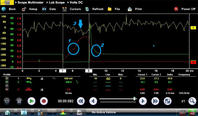
- Yellow channel: fuel injector supply circuit
- Green channel: fuel injector control circuit
- Red channel: fuel injector current flow
The green trace shows the injector control circuit voltage.
When the injector is switched off, open circuit voltage (system voltage) is present on this wire, as the path to ground through the engine ECM is open.
Once the ECM completes the circuit this wire is “pulled” to ground, since a potential difference is now present across the injector winding current will begin to flow.
The current “ramps” up slowly due to the inductance (resistance) of the injector winding.
At point 1 a change in the profile (knee point) of the trace will be observed, this is due to the pintle valve opening fully.
Absence of this knee point is an indication that the injector either didn’t open or is stuck open i.e. no movement has taken place.
The cursors on the trace indicate the injection duration, in this case 3.13 milliseconds.
When the injector is to be switched off the ECM opens the path to ground and current flow ceases.
This induces a Back EMF (Electro-Motive Force) into the winding and a voltage of 60 to 80 volts is observed.
The engine ECM uses the presence of this voltage to validate the electrical operation of the injector. OBD codes P020x will be stored if there is an anomaly with this induced voltage.
Point 2 on the waveform shows a slight change in the voltage profile of the trace, which indicates that the pintle is now fully closed.
This is more subtle than in the current trace, so testing multiple injectors on the same engine is recommended to remove ambiguity.
Point 3 displays the yellow trace on the waveform. This is the injector supply voltage, coupled to AC to clearly see the voltage drop. When current flows within a circuit a voltage drop is created.
This trace shows a voltage drop of approximately 100 milliVolts for a current flow of 800 milliAmps. This is acceptable.
The image below shows a diagram looking at all factors which take place when the injector is actuated:
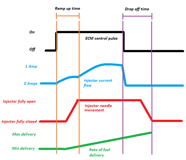
- Black: injector control circuit
- Blue: injector winding current flow
- Red injector pintle valve movement
- Green: fuel delivery
It can be seen from this graphic that there is a delay in the opening and closing of the fuel injector due to the inertia of the pintle valve.
This is factored into the ECM calculation for the optimum injector pulse width.