Some modern vehicles use priority lighting to ensure the vehicle stays illuminated in the case of a bulb or circuit failure. When this system is used, all bulbs fitted to the rear light clusters are 21 Watt bulbs. A control module, normally fitted in the rear of the vehicle, controls the operation of all rear lights. During tail light operation, a 21 Watt bulb is controlled by ≈25% Duty Cycle to provide an output similar to a 5 Watt bulb. It must be noted that the bulbs are controlled on the supply side and have a constant ground.
Should a bulb fail, the Control Module can use another bulb to ensure the vehicle is still illuminated correctly.
The diagram below shows a basic overview of the system.
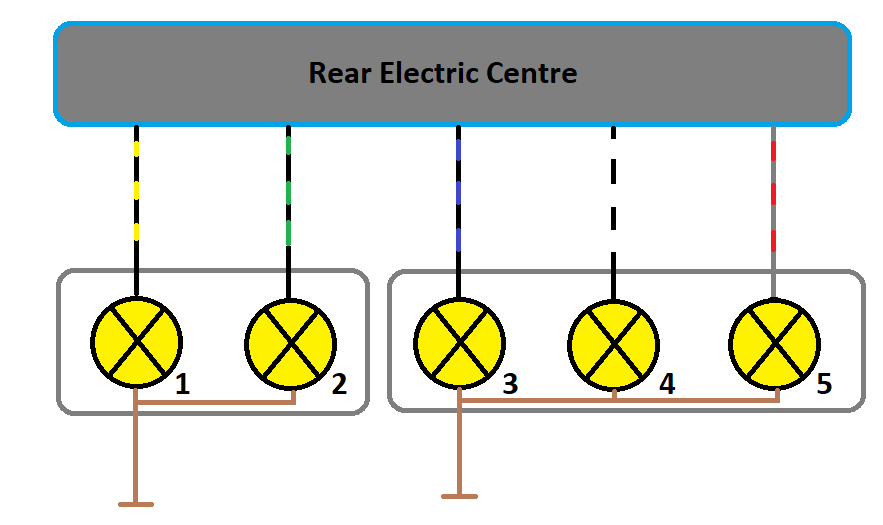
Right hand rear light cluster:
- Brake Light
- Indicator Light
- Fog Light
- Reverse Light
- Tail Light
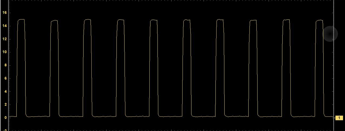
The waveform below shows the duty cycle for tail light operation.
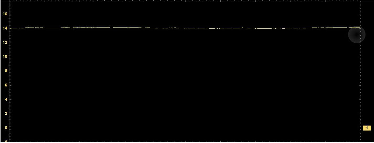
Full system voltage is applied to a bulb for the following operations:
- Brake Light
- Fog Light
- Reverse Light
Connecting a scan tool to a vehicle with a fault may indicate a similar malfunction to the case study below:
B3878 - Right Brake Light Circuit Open or High Voltage
An oscilloscope was connected to the output from the Control Module to the right hand brake light bulb, which was illuminated, a voltage of 12 volts was present on the wire at all times with and without the brake pedal depressed. The wire was tested for a short to positive, the integrity of the wire was found to be acceptable. This indicated a fault within the Control Module. The module was replaced and programmed/configured. The fault memory was cleared and the operation of the brake lights tested. The vehicle now behaved as expected.
Make sure you sign up to our monthly Technical Focus articles in the side-bar!