Sometimes a vehicle will suffer from driveability issues and fault codes relating to valve timing. Such conditions can be difficult to diagnose without the correct equipment.
The purpose of variable valve timing (VVT) is to help increase the engine’s volumetric efficiency and limit the exhaust gasses produced by the vehicle. By altering when the valves open and close you can optimize the performance of the engine.
Using an actuator test a technician can actuate a variable valve timing solenoid and observe a change in the audible note of the engine and/or a change in engine speed.
To demonstrate let’s take a look at an example.
This particular Toyota Auris (Corolla) with a 1NR-FE engine has variable valve timing on both intake and exhaust camshafts. For the purpose of this article the exhaust camshaft timing control solenoid has been actuated. During the functional test, the technician is presented with data. See image 1 below:

Image 1
During actuation of the solenoid valve it can be seen that the engine speed dropped to 587 Revolutions per Minute (RPM), the Electronic Throttle Control system increased the engine speed to prevent a stall so the engine speed increased to 812 RPM before stabilizing at 737 RPM when the actuator test finished.
Taking a closer look
Using an oscilloscope the technician can view the actual change in camshaft position with respect to the crankshaft and the camshaft which hasn’t been actuated.
Image 2 presents a waveform that shows a trace at idle with 0% actuation of the exhaust solenoid. The table below shows the signal being displayed on each channel:
| Channel Number |
Channel Colour |
Signal |
| 1 |
Yellow |
Ignition coil cylinder 1 control |
| 2 |
Green |
Exhaust camshaft position |
| 3 |
Blue |
Crankshaft position |
| 4 |
Red |
Intake camshaft position |
The ignition coil trace is used as a trigger to capture the waveform and to reference cylinder position. With the engine at operating temperature and the engine idling, the ignition advance angle will be approximately 6 to 8° of crank angle rotation before Top Dead Center.
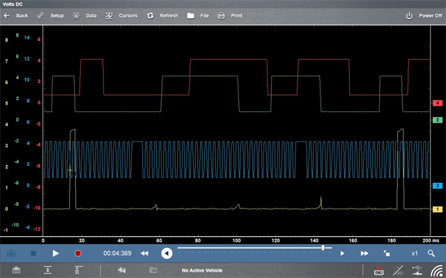
Image 2
The phonic wheel for detecting the crankshaft speed and position has 34 teeth with two missing teeth to indicate crankshaft position with respect to Top Dead Center (TDC).
The waveform, Image 3 below, shows the same trace during the actuator test.
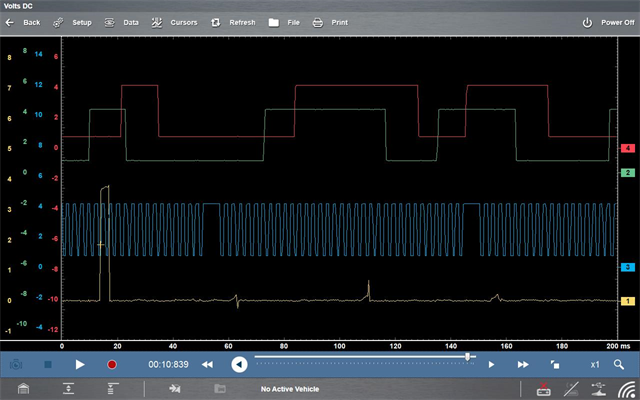
Image 3
The camshaft can be retarded by a range between 10-30° of crank angle rotation.


Normal Idle, During the actuator test
The waveform can be used to validate the operation of the entire variable valve timing circuit, not only electrically but also mechanically and hydraulically.
Which is key to testing the dynamic valve timing of the engine.
In-Cylinder Pressure Testing
A pressure transducer can be used to analyze the in-cylinder conditions with the engine running. This test can be used to inspect the valve timing as well as detecting issues with cylinder sealing. Image 4 shows the expecting waveform with the engine idling.
The table below shows the signal being displayed on each channel:
| Channel Number |
Channel Colour |
Signal |
| 1 |
Yellow |
In-cylinder Pressure |
| 2 |
Green |
Crankshaft Position Sensor |
| 3 |
Blue |
Crankshaft Position Sensor |
| 4 |
Red |
Variable Valve Timing Solenoid |
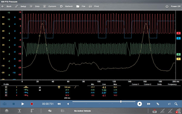
Image 4
From the waveform above we can see the Variable Valve Timing solenoid valve has a low duty cycle, approximately 10% actuation. It must be noted that the solenoid valve has a constant ground and is controlled on the positive side.
The waveform below, image 5, shows the change in camshaft position when the Variable Valve Timing solenoid is supplied with a constant live.
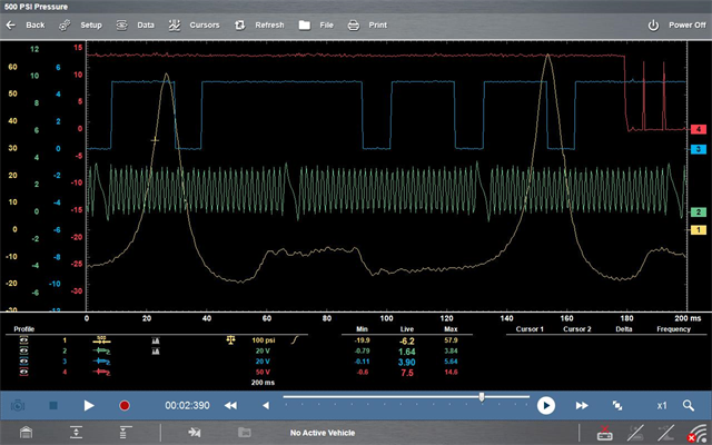
Image 5
Thus movement equates to approximately 30° of crankshaft rotation. Note, the engine may stall during this test.