This Toyota Prius had malfunction warning lights illuminated and two faults relating to the High Voltage System stored.
| Module |
Code |
| Hybrid Control Module |
P3000 Battery Control System. |
| HV Battery Control Module |
P0AFA Hybrid Battery System Voltage Low |
Intermittently the vehicle would not enter “Ready Mode” and the High Voltage System would remain inactive as the high voltage contactors (System Main Relay SMR 1, 2 and 3) were not being switched on by the High Voltage Control Module.
The system has three SMRs
- SMR 1: Positive Contactor
- SMR 2: Pre-charge Contactor
- SMR 3: Negative Contactor
The Pre-charge function is to limit the initial supply of current from the High Voltage Battery to the Inverter.

Sequence of operation of SMRs:
| Ready On |
|
|
|
| |
SMR 1 |
SMR 2 |
SMR 3 |
| Stage 1 |
Off |
Off |
Off |
| Stage 2 |
Off |
On |
On |
| Stage 3 |
On |
On |
On |
| Stage 4 |
On |
Off |
On |
| High Voltage System Off |
|
|
|
| |
SMR 1 |
SMR 2 |
SMR 3 |
| Stage 1 |
On |
Off |
On |
| Stage 2 |
Off |
Off |
On |
| Stage 3 |
Off |
Off |
Off |
As the High Voltage Battery is located in the luggage compartment and access is difficult, live data was used to monitor the battery voltage for each battery block. The High Voltage battery is made up of 14 x 14.4V blocks. Each block is made up of 2 x 7.2V cells. This equates to a total voltage of 201.6 volts. Anything over 60 volts Direct Current (DC) is considered high voltage. So, precautions must be taken when working on such a vehicle, appropriate training, PPE, insulated tooling, etc.
IMPORTANT: A High Voltage system must only be worked on by suitably qualified technicians.
The High Voltage Service Plug must be removed and the system allowed adequate time to de-energize prior to carrying out work on the system.
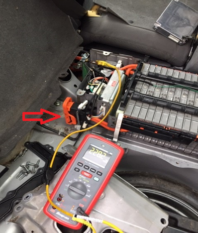
The arrow above shows the high voltage service plug.
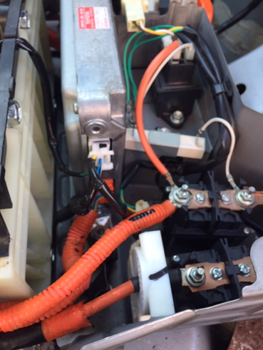
Each battery block has a sensing wire attached to a negative stud, which is wired to the High Voltage Control Module.
The diagram below shows three blocks as an example.

- Battery Block 1 sensing wire
- Battery Block 2 sensing wire
- Battery Block 3 sensing wire
- High Voltage Battery Control Module
- High Voltage Cable
- Cell (Negative Connection)
- Cell (Positive Connection)
- Battery Bus Bar
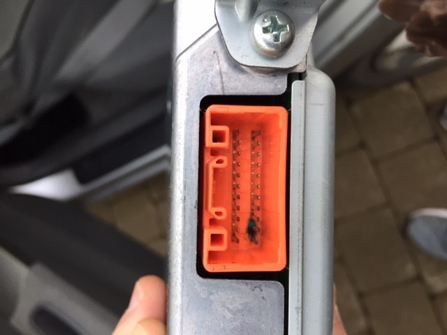
High Voltage Battery Control Module and Current Clamp (white component) on Negative Wire.
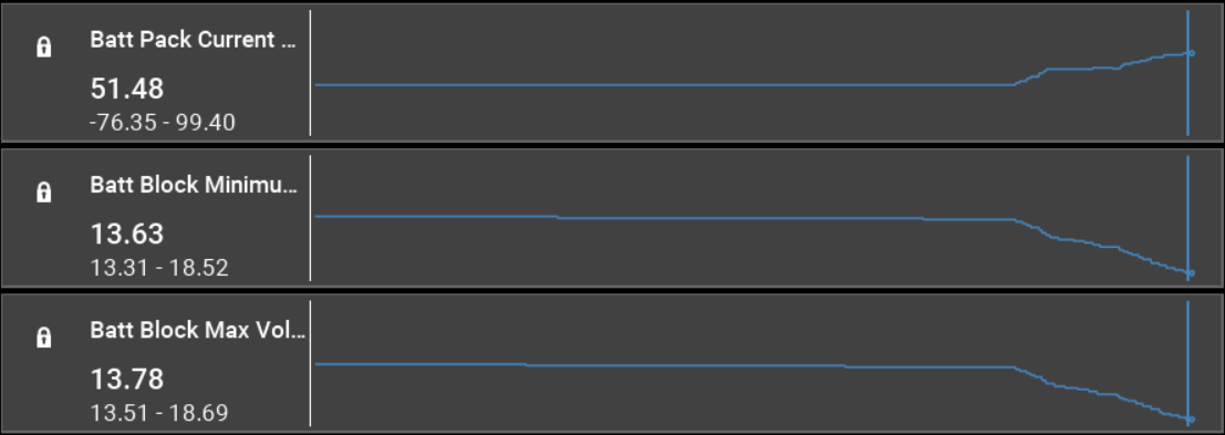
The Screenshot below shows the data observed for four of the fourteen battery blocks.
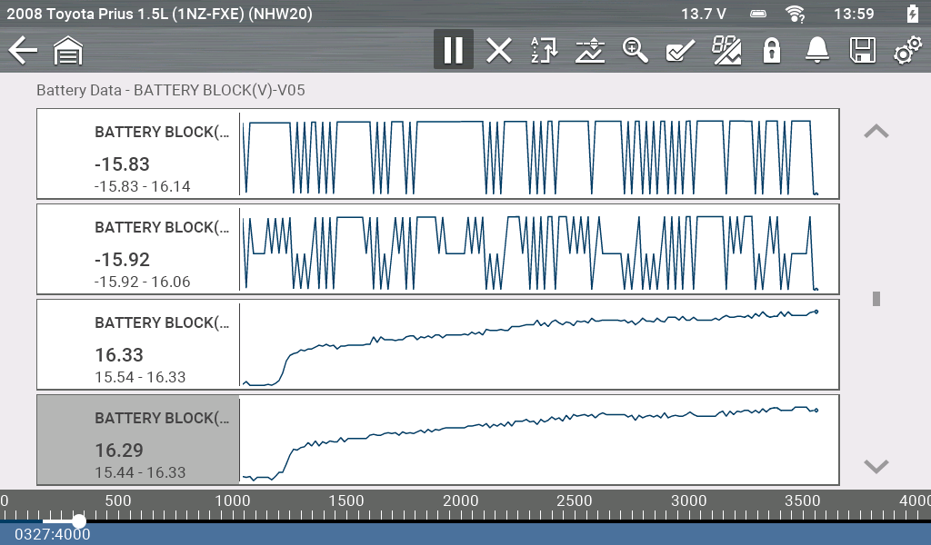
The first two graphs are erratic and not behaving like the other two. The voltage had an irregular cycle between 16 volts negative and 15 volts positive. This condition isn’t possible. So further investigation was required, which required disassembly of the battery casing.
The bus bars connecting the battery cells were found to be corroded so were removed and cleaned. The wiring and connections associated with the battery block sensing circuits were inspected and cleaned, also.
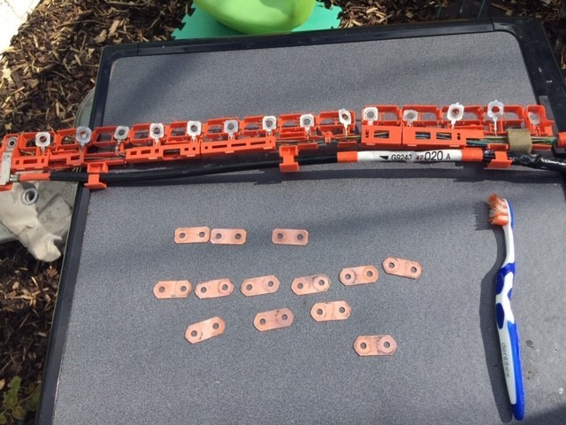
Once the system was reassembled and powered up the fault was found to still be present. Next, the connections on the High Voltage Battery Control Module were inspected and it was found. Three of the pins on the module were badly corroded.
This module was replaced and the fault codes cleared. The live data now displayed the correct voltage of each battery block.
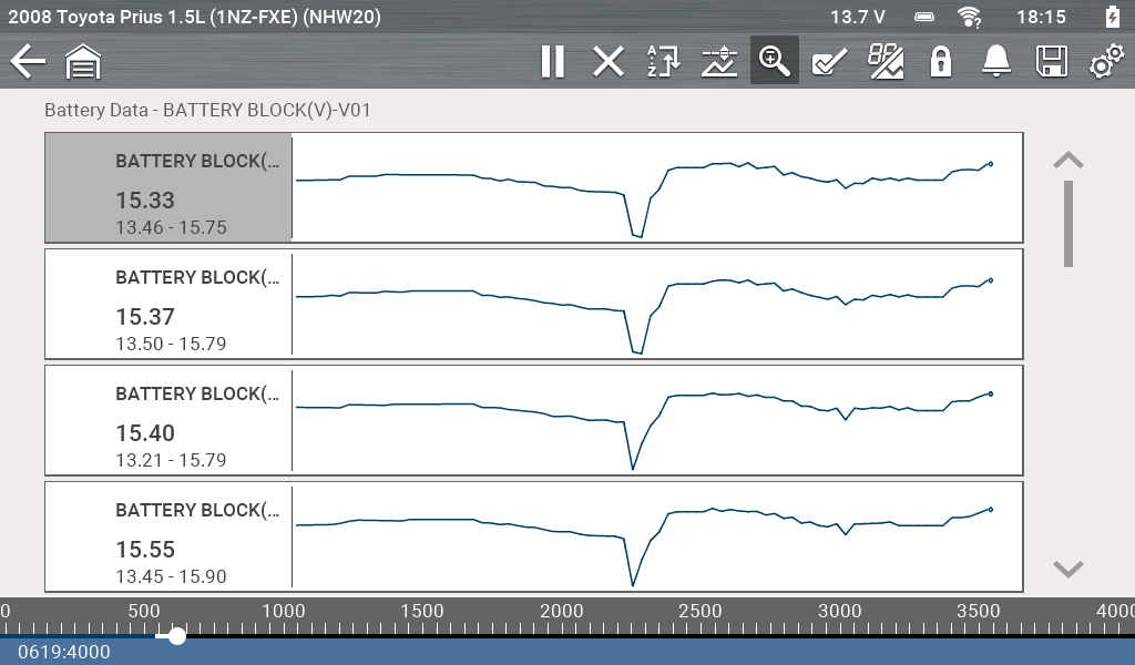
The image above shows the voltage for four battery blocks under hard acceleration, this results in a noticeable voltage drop on each block. All fourteen blocks should return a similar voltage under all conditions, full-electric mode, hard acceleration and regenerative braking.
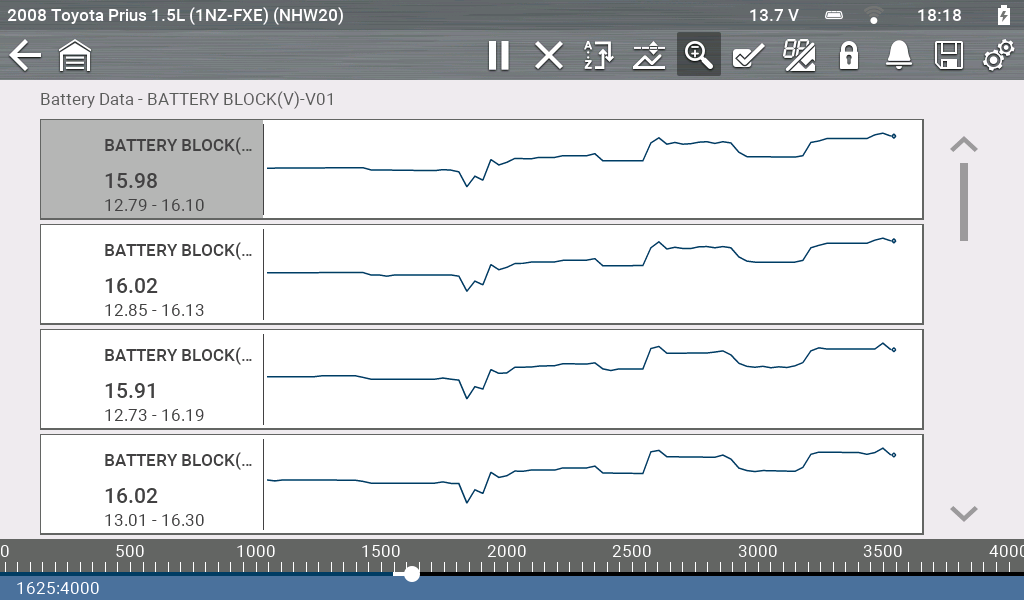
The image above shows the voltage for four battery blocks under regenerative braking, this results in a voltage increase on each block.
The Prius information display shows the driver the current driving mode through the Energy Monitor, which is helpful for fault finding. States are as described:
- Normal Driving – ICE operating
- Vehicle operating in full electric mode
- High Voltage Battery being charged through Regenerative Braking
Monitoring High Voltage Battery Condition:
While road testing the vehicle we can check the condition of the High Voltage Battery under certain operating conditions.
Regenerative Braking:

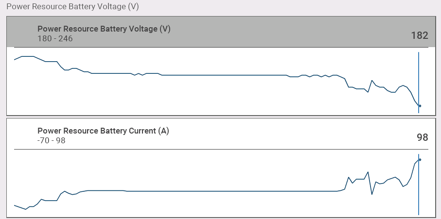
EV Mode:

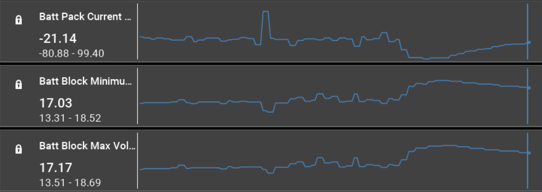
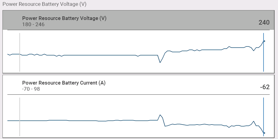
During this test, we are looking for a difference of no greater than 0.3 volts between any of the battery blocks under load.
The image below shows the relationship between current and voltage under both conditions.
Regenerative Breaking:
EV Mode:
After road testing the vehicle and carrying out a Post Scan with the diagnostic tool, the vehicle was returned to the customer.