What is CAN bus?
CAN High CAN Low
CAN Bus Voltage Levels
CAN Bus Waveform Analysis
CAN Bus Case Study Example
Introduction
What is CAN bus?
Controller Area Network (CAN) is a data transfer network designed to allow many nodes (modules) to communicate using a standard structure and format. This has the benefit of reducing vehicle wiring and allowing additional vehicle options to be added or removed easily. Troubleshooting such a complex system is reasonably straightforward once the technician has a basic understanding of the network and how data is transferred. This article will provide the technician with the necessary tools to successfully validate a CAN bus signal and help to identify faults where present.
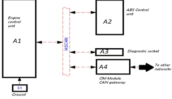
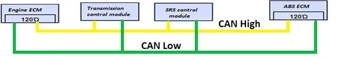
Basic block diagram of a typical CAN Network.
CAN High CAN Low | Characteristics of a high speed CAN network (Class-C)
Multiple modules are connected to the bus in parallel. The data transfer rate is 500K bits/sec for high speed CAN. That’s 500,000 pieces of data or information per second!! The signal is broadcast over two communication wires to ensure signal integrity is maintained, these wires are twisted together and are referred to as CAN High and CAN Low.
To ensure messages of the highest priority are transmitted first, an arbitration field is part of the message structure. To ensure optimum signal quality, two fixed value resistors are connected to the bus to condition the signal. These are referred to as terminating resistors.
All these characteristics will be described in greater detail below.
Signal Generation
Each module on the network has a CAN controller and a CAN transceiver on the CAN chip. A transceiver has the ability to both transmit and receive data. The CAN controller converts data (binary) sent from the microprocessor and sends it to the CAN transceiver. The CAN transceiver converts the binary data into a voltage range and this is the signal voltage observed on the network.
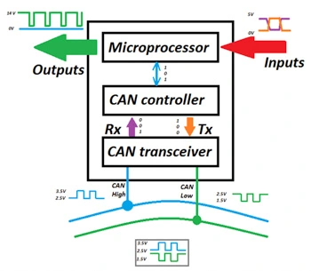
Note: Inputs and outputs to a module are still analog. A component such as a throttle motor will still require supplies, grounds and feedback signals as with a non-CAN vehicle.
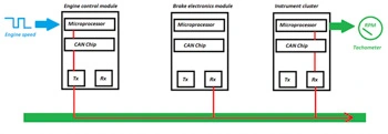
The diagram below illustrates how a message received by the engine control module is processed and transmitted on the network for other modules. In this example the engine speed input from the crankshaft position sensor to the engine ECM is also required by the Instrument cluster for the tachometer.
CAN Bus voltage levels
The table below shows the expected voltage for both recessive and dominant states on the CAN High and CAN Low wires.
| State |
CAN High voltage |
CAN Low voltage |
Bit type |
| Recessive |
2.5 volts |
2.5 volts |
1 |
| Dominant |
3.5 volts |
1.5 volts |
0 |
Using an oscilloscope, the following voltage levels can be observed when connected to a network.
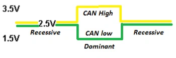
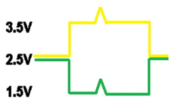
As mentioned previously both CAN High and CAN Low are twisted together to reduce external interference. The diagram below shows the differential voltage between CAN High and CAN Low during data transfer.
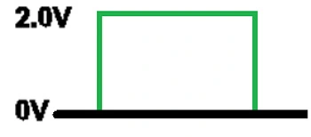
With a recessive bit, both CAN High and CAN Low voltage levels are at 2.5V so the differential voltage is 0 volts. When a dominant bit is transmitted, CAN High rises to 3.5V whereas CAN Low drops to 1.5V. This is a differential voltage of 2 volts.
In the event of a transient condition occurring, such as an external voltage spike both CAN High and CAN Low will be similarly affected. So the differential voltage will remain at 2 volts, this protects the integrity of the message.
CAN bus waveform analysis
The waveform below shows both the signal when CAN High and CAN Low are tested with respect to ground and the differential voltage between CAN High and Can Low. Example shown from a Volvo XC-90.
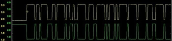
- Both traces mirror each other
- Clean without glitches or spikes
- Correct voltage
- Correct differential voltage
Note: A technician may observe an increased voltage on a trace at the end of a message. This is the End of Frame bit and is not a cause for concern.
Signal reflection protection
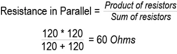
Due to the high data transfer rate a means to dampen signal reflections is required. To achieve this manufacturers use two 120 Ohm resistors in parallel. Although some vehicle applications have the resistors located externally in the wiring loom, most locate the resistors in two separate modules, as shown below.
With both resistors equal in resistance and wired in parallel, the total circuit resistance is halved.
Message Arbitration
With CAN bus it must be noted that the message carries the priority, not the module ID. A message with the lowest numerical identifier, most dominant bits (0), can transmit message. All modules listen until the bus is idle again before transmitting. See the example below.
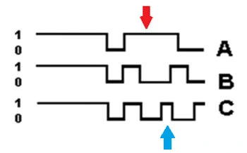
Module A loses the chance to send out its message first (Red arrow).
Module C loses the chance to send out its message second (Blue arrow).
Module B wins arbitration.
Case Study - Open Astra
This vehicle wouldn’t start, as terminal 50 on the starter motor solenoid was not receiving current when the ignition key was turned to the start position. Also there was no communication with the Engine Management control module, Instrument cluster, Anti-Lock Brake Control module or Steering Column Integration module (CIM) using a scan tool. These modules are on the high speed CAN bus. The vehicle had a flat battery and a technician attempted to start the vehicle unsuccessfully.
An oscilloscope was connected to pin 6 and pin 14 of the vehicle Data Link Connector (DLC) to access the high speed network.
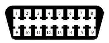
Pin assignment:
- Pin 4: Chassis ground
- Pin 5: Signal ground
- Pin 6: CAN High (ISO 15765)
- Pin 14: CAN Low (ISO 15765)
- Pin 16: Constant supply (+12 volts)
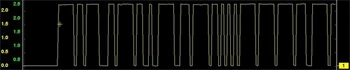
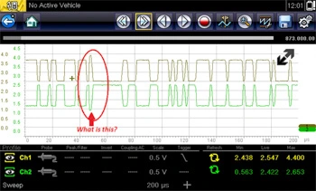
The following waveform was captured:
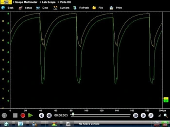
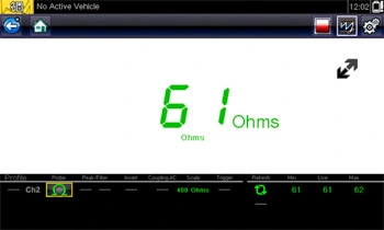
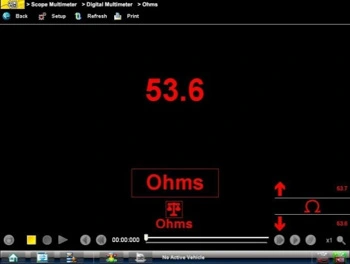
Testing the resistance of the network showed a short circuit:
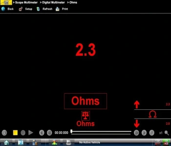
As the issue was most likely as a result of a damaged electronic control module, each module on the high speed network was disconnected in turn until the network signal returned to the waveform expected. When the Anti-Lock Brake module was disconnected the oscilloscope displayed the following waveform:

The vehicle now started and the scan tool was capable of communicating with the Engine Control Module, Instrument cluster and the CIM. The network resistance also returned to specification:
Basic systems controlled using CAN bus:
The diagram below illustrates how a basic system such as the starter motor has changed since CAN bus technology has been implemented on vehicles. The start signal from the ignition switch is sent to the Steering Column Module, once processed it is converted to a CAN message and transmitted on the CAN network. The Engine Bay fuse box uses this message to control the starter motor relay by grounding terminal 85 of the relay winding. This results in the relay contacts closing and supplying current to terminal 50 of the starter motor solenoid.
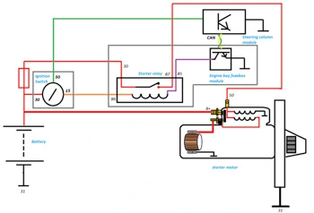
It can be seen that the internal electrical circuit of the starter motor remains unchanged.
Pin assignment:
- 30 – Constant Live
- 31 – Ground
- 15 – Ignition on Live
- 50 – Starter motor solenoid control
- 86 – Starter motor relay winding supply
- 85 – Starter motor relay winding ground control
- 87 – Starter motor relay contacts output
Gateway Module
A Gateway module is used to allow modules on different networks with different data transfer speeds to communicate. The Gateway is the link between multiple networks. The module can be a separate module or part of another module such as an instrument cluster module.
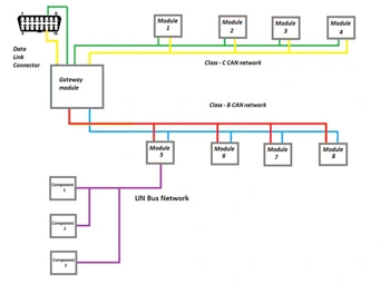
The example above shows the high speed Class C CAN network (500 kBits/second), the comfort Class B CAN network (250 kBits/second) and the Lin Bus local network (10 kBits/second) all capable of communicating via the gateway module.