What is an EGR Valve?
How Does an Open EGR Valve Impact an Engine?
Common EGR Fault Codes
Testing an EGR Valve
What is an EGR Valve?
An EGR (Exhaust Gas Recirculation) valve is an emission control device found in modern internal combustion engines. Its purpose is to reduce the amount of nitrogen oxides (NOx) produced by the engine, which are harmful to the environment.
How Does an Open EGR Valve Impact an Engine?
When the EGR valve is open, a controlled amount of exhaust gas is allowed to enter the combustion chamber alongside the incoming air-fuel mixture. This process has several effects on the engine:
1. Reduction in combustion temperature: The introduction of exhaust gas into the combustion chamber lowers the peak flame temperature during the combustion process. This decrease in temperature helps inhibit the formation of NOx, which is typically produced at high combustion temperatures.
2. Dilution of air-fuel mixture: The exhaust gas contains inert gases, such as carbon dioxide (CO2), which do not participate in the combustion process. By mixing these inert gases with the incoming air-fuel mixture, the overall oxygen concentration in the combustion chamber is reduced. This results in a leaner mixture, which can help reduce the formation of harmful pollutants.
3. Increased cylinder pressure and efficiency: The addition of exhaust gas into the combustion chamber increases the total mass of gases present during combustion. This leads to an increase in cylinder pressure, which can enhance the engine's thermal efficiency and power output.
Common EGR Fault Codes:
On later models of EGR valves, the following codes are most common:
P0400: EGR flow malfunction
P0401: EGR insufficient flow detected
P0402: EGR excessive flow detected
P0403: EGR circuit malfunction
P0404: EGR circuit range/performance
The Clear View Flag Tracker is a feature that can help a technician to identify when a data parameter (PID) value goes out of specification. Let's take a look at how a technician can use this exclusive Snap-on feature to quickly diagnose a faulty EGR position sensor.
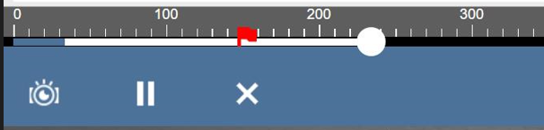
A minimum and maximum value can be set for a particular Data Parameter (PID) and if either the upper or lower limit is exceeded a solid red line will appear on the data graph on the PID. The other data parameters will have a dotted line at the point where the limits were breached.
Also a red flag is dropped on the X-axis at the time the PID is breached. This makes it easy for a technician to quickly identify when the issue occurred and return to that point in the data buffer. Clicking the flag will bring the graph back to that point in the buffer.
Below is an example that shows how a technician would use this feature to diagnose a faulty EGR Position Sensor circuit.
A vehicle has an EGR Position Sensor circuit fault code. The position sensor has a 5 volt supply, ground and a signal which ranges from 0.9 volts (EGR Valve fully closed) and 3.9 volts (EGR Valve fully open).
Case Study - Testing an EGR Valve
A 2003 Honda Accord 2.0L petrol with engine code K20A6 experienced an illuminated engine management light and a fault code indicating "EGR – Insufficient flow detected."
To understand this issue, it's important to know that this vehicle uses a speed density system, which relies on inputs from the manifold absolute pressure (MAP) sensor, throttle position sensor, and engine speed sensor to calculate engine load.
In this particular engine, the EGR valve and MAP sensor are easily accessible, making testing the system straightforward. After reading the diagnostic fault codes, I performed an actuator test on the EGR valve. I could hear the valve moving inside the housing, and there were no unusual noises from the valve body.
To further investigate, I connected a volt meter to the EGR position feedback signal wire. When the valve was closed, a voltage of 0.7 Volts was present on the signal wire, and when fully open, a voltage of 3.5 Volts was present. This confirmed that the EGR valve was functioning as expected.
The next step was to actuate the EGR valve while monitoring the output from the MAP sensor. Surprisingly, there was no increase in voltage when the EGR valve was fully open, indicating that the manifold pressure remained unchanged.
This observation revealed that the problem lay with the flow of exhaust gas from the exhaust manifold, through a port in the cylinder head, into the intake manifold.
To verify this, I removed the EGR valve and started the engine. I noticed that exhaust gas was present at the EGR valve. However, when the valve was removed from the intake manifold, the engine speed should have increased due to the intake manifold being exposed to atmospheric pressure. This indicated a blockage on the intake manifold side of the EGR valve.
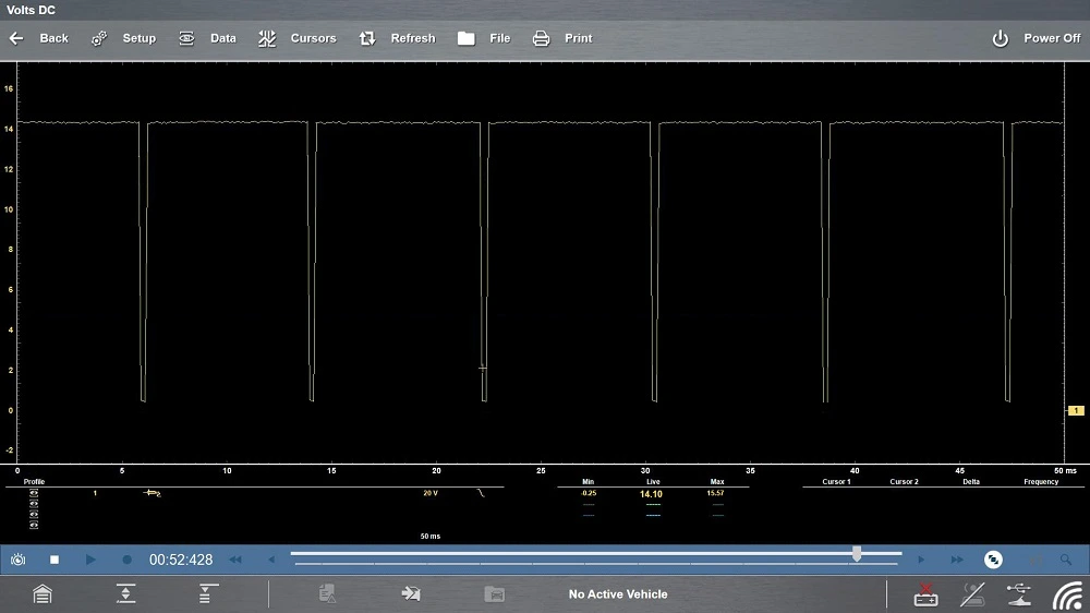
Below shows an image displaying EGR position feedback voltage and MAP sensor signal voltage, both pre- and post-repair.

The blue line is the MAP sensor signal voltage and the green line is the EGR position feedback voltage. The post-repair image shows that the MAP signal voltage increases to 4.5 Volts.
This is because the engine cut out due to the high rate of EGR when the valve was actuated. This further confirmed the diagnosis.
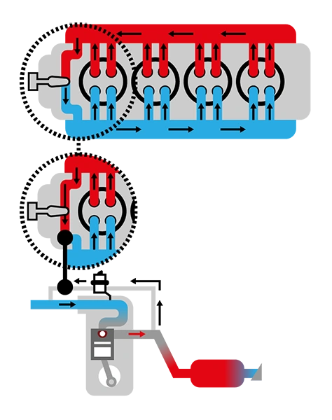
This image shows in detail the effect the blockage had on the gas flow circuit.
*Due to increasingly stringent emissions regulations over the last number of years, manufacturers have had to look to additional technology to meet these requirements.
One of the harmful exhaust gas constituents, which need to be reduced, is oxides of nitrogen or NOx gases. Oxides of nitrogen are not only responsible for adverse effects on the environment but can also contribute to respiratory conditions in the population.
The ambient air is made up of 78% Nitrogen, 21% Oxygen and 1% of other gases (including argon and carbon dioxide).
The available nitrogen does not contribute to the combustion process within the combustion chamber.
However, during comparatively lean running conditions, there is a surplus of oxygen. The nitrogen and surplus oxygen react in the presence of elevated combustion temperatures to create NOx gases.
Currently there are several ways to reduce NOx emissions:
- Exhaust gas recirculation valve (external EGR)
- Variable valve timing (internal EGR)
- Selective catalytic reduction system (NOx accumulator)
For the purpose of this document the (external) EGR system will be explained and the remaining two methods will be addressed in the next document.
In order to reduce the formation of NOx gases an EGR valve can be fitted. The EGR valve regulates the quantity of (spent) exhaust gases recycled into the intake manifold.
This method works effectively because the recycled exhaust gases are inert and essentially “dilutes” the fresh mixture charge. The result is the overall peak combustion temperature is reduced.
The EGR system is operated during conditions where there is a surplus of free oxygen such as part load and cruising conditions.
The EGR system must be closely monitored for malfunctions, and adequate diagnostic fault codes must be available. Electrical faults and mechanical defects must be easily identifiable.
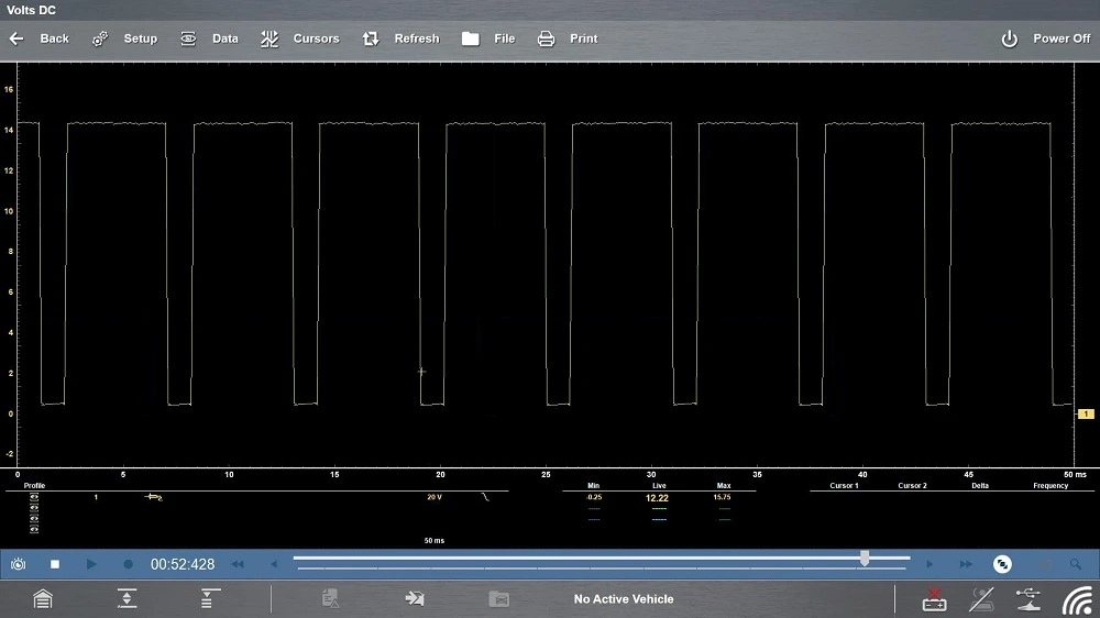
The EGR control solenoid is normally variable PWM (pulse width modulation) control, and this can often be referred to as a duty cycle.
This is a digital control system, which allows greater control of valve position and the overall current consumed by the solenoid is reduced.
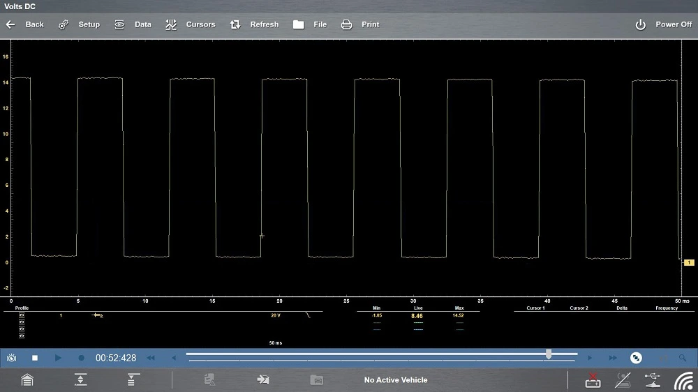
Below are examples of different PWM controls for a solenoid with a constant ignition on supply and a ground control via the engine control module.
EGR valve position is monitored by using a potentiometer, normally integrated into the EGR valve assembly. This sensor creates a feedback voltage which the ECM can interpret and determine the position of the valve.
A fault code will be generated if the ECM’s position command and feedback position differ.
Exhaust gas flow can be determined in one of two ways, depending on the vehicle. Some systems use a mass airflow meter to calculate load by monitoring airflow volume (and density) entering the engine.
Other systems use the speed density method, which uses inputs from the manifold absolute pressure sensor, throttle position sensor and engine speed sensor to calculate engine load.
If an engine management system uses a mass airflow meter, a reduced quantity of incoming airflow will be observed while exhaust gases are being recycled. This is due to the recycled exhaust gases “taking up space” in the intake system.
If the speed density system (on a spark ignition engine) is used by an engine management system an increase in intake manifold pressure will be observed while exhaust gases are being recycled.
This is most evident on over-run conditions, where the throttle is closed and the engine speed is comparatively high, a large depression/negative pressure is present in the intake manifold. If the EGR valve is actuated during this condition an increase in manifold pressure will be observed.
Below is a table of common fault codes associated with the EGR circuit.
| Code ID
|
Code Title
|
| P0400
|
EGR "A" Flow
|
| P0401
|
EGR "A" Flow Insufficient Detected
|
| P0402
|
EGR "A" Flow Excessive Detected
|
| P0403
|
EGR "A" Control Circuit/Open
|
| P0404
|
EGR "A" Control Circuit Range/Performance
|
| P0405
|
EGR Sensor "A" Circuit Low
|
| P0406
|
EGR Sensor "A" Circuit High
|
The image below is a circuit layout of an EGR valve with an integrated position sensor.
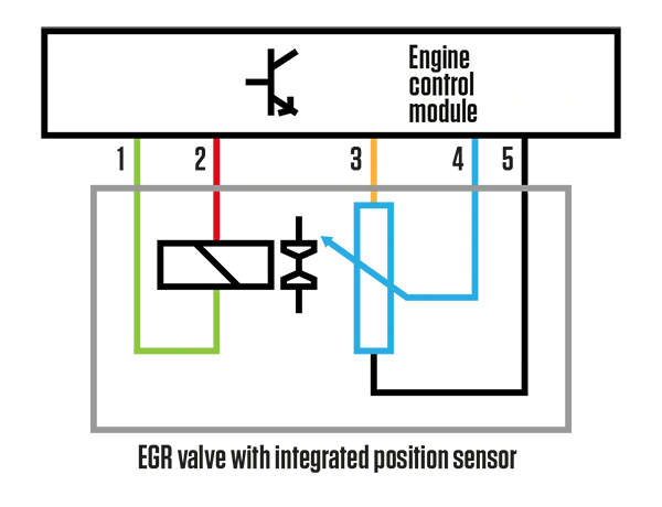
- EGR solenoid PWM controlled ground circuit
- EGR solenoid constant supply, at system voltage
- EGR valve position sensor 5V reference voltage
- EGR valve position sensor feedback voltage
- EGR valve position sensor ground circuit