There are many systems and functions in the modern motor vehicle that require a method of controlling and reversing the electrical polarity of a circuit. The most common process is controlling the direction of rotation of a motor, e.g. electric window motor, electric power steering motor, electronic throttle control motor, etc.
Electronic throttle control has now become standard fitment on all spark-ignition engines. This has allowed for advancements in technology such as cruise control, traction control, limited operating strategy (limp home mode), and engine speed limiter. Although these functions previously existed, electronic throttle control has further refined the operation of the vehicle, complementing these functions.
Another advantage of electronic throttle control has been seen in vehicles with direct fuel injection that can function in two modes: homogeneous and stratified. Homogeneous mode is when the engine runs on a stoichiometric air to fuel ratio of 14.7:1, and fuel is injected late on the exhaust stroke/early on the intake stroke. The fuel and air mix give a homogenous fuel mixture.
Stratified mode is when fuel is injected late on the compression stroke, and the mixture formation is heterogeneous. Please see the diagram below:

On the diagram above, the blue circles represent air, and the red circles represent fuel. You can see that the mixture is exceptionally rich in the center of the heterogeneous mixture, but overall, the mixture is lean. Under stratified running mode, the throttle valve is held fully open and the driver demand (accelerator pedal input) is varied by adjusting the quantity and pressure of the fuel being delivered. Without electronic throttle control, this functionality would be at best, extremely complex, or more realistically, would be impossible as there has to be a complete disconnect between the accelerator pedal input and the control of the throttle valve.
Vehicles fitted with electronic control can precisely control idle speed and also use additional processes such as closing the throttle valve slightly under cranking to improve engine start-up. This is controlled by changing the electrical polarity of the throttle motor. The image below shows a basic electronic throttle control system:
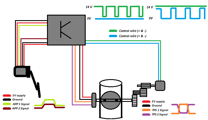
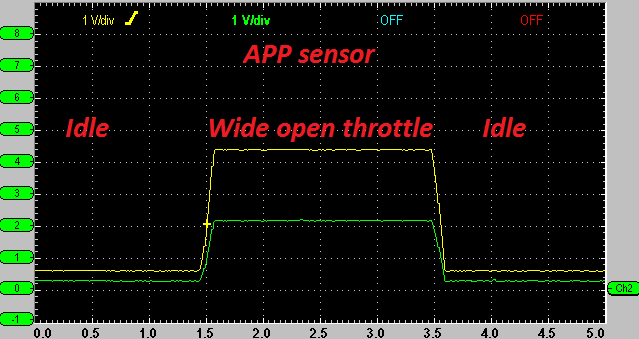
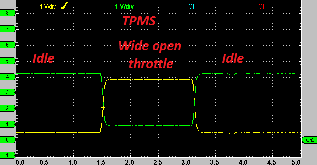
Shown in the image above, accurate monitoring of the accelerator pedal position (APP) and throttle motor position (TPMS) are required. These sensors have two/three outputs for redundancy and fault detection. In the case of a single track/circuit failure, then the system can still function. Electrical short and open circuits can easily be detected. Below is an example of both APP and TPMS position sensor waveforms.
Motor Control
As had previously outlined, the polarity of the motor is reversible which allows accurate control of the entire system. A way to control the polarity is by designing a circuit referred to as an “H-drive” bridge circuit. The bridge circuit can be created using IGBT (Insulated Gate bipolar junction transistors) or MOSFETS (metal oxide field effect transistors). The latter being the most common way of controlling such a circuit. A control circuit using mechanical switches is shown for demonstration purposes.
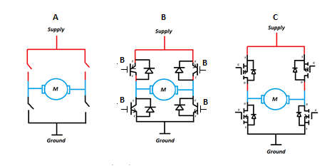
- Mechanical Switches
- IGBTs
- MOSFETs
Below are two images which demonstrate the fundamental operation of the circuit, basic mechanical switches are used to simplify the circuit:
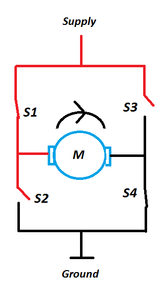
With switches “S1” and “S4” closed the current flow through the motor results in the motor rotating clockwise.
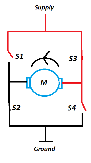
With switches “S2” and “S3” closed the current flow through the motor results in the motor rotating counter-clockwise.
Please note: If switches “S1” and “S2” or “S3” and “S4” are closed simultaneously then the motor will be short circuited and the circuit may be damaged.
Feedback and Control
As previously outlined, the engine control module uses the feedback from the accelerator pedal position sensor to determine driver demand. Vehicle demands may also exist in the form of a traction control system command or from the engine speed limiter. However, for correct operation of the electronic throttle control motor, a closed loop control system must be implemented using throttle position sensors.

In this simplified example, an operational amplifier voltage comparator uses inputs from both the desired throttle position and actual throttle position. The output (Vo) from the comparator is the voltage difference between both signal voltages applied. This output voltage is used to control a PID (proportional, integral, derivative) driver which then outputs a PWM (pulse width modulated) control to the H drive circuit.
Current Flow and Voltage Waveform Analysis
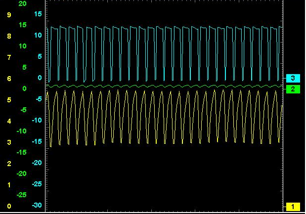
Below are oscilloscope waveforms captured from a vehicle. The yellow trace is the current flow through the motor and both the green and blue traces are the motor voltage control wires with a hard ground as the reference for the oscilloscope.

We can see from the above waveform when the voltage on both wires is equal there is no current flow through the motor. Then one wire is given a ground (green trace) and the other with is controlled with a PWM command. The more positive the PWM, the greater the current flow will be. This particular trace illustrates the point.

This image is similar to the previous waveform. However at the beginning of the trace the wire being tested with the green trace is given a “hard” live and the other wire is controlled with a PWM, this time on the ground side of the control. This has the effect of reversing the polarity of the current flow through the motor. After a period of time the polarity of the control voltage changes and the current flow becomes positive. Again note the increase in current flow as the PWM supply increases.

This waveform shows the current flow switching from negative to off when the ignition is switched off. The voltage is held at approximately 5 volts. This voltage can be used to monitor the system for faults and open/short circuits. Please note that some electronic throttles will only be actuated when the engine is running or cranking as opposed to key on, engine off.

This waveform is similar to the previous trace with the exception that the current flow is positive before the system is shut-off.

This image shows a low PWM which results in a reduction in current flow through the throttle motor. Note in the middle of the trace both control wires are given a “hard” ground which causes current flow to cease. This is to allow constant control of the throttle valve and to allow for smooth operation and controlled idle. The PWM is approximately 10-15% and the average voltage is 1 Amp.
The final waveform shows a comparatively large positive PWM control which increase current flow through the motor, resulting in a greater throttle valve angle. The PWM is approximately 80-85% and the average voltage is 4 Amps.