Modern vehicles contain more electronic modules than ever before, but few have expanded their responsibilities as dramatically as the body control module (BCM). What began as a controller for vehicle lighting, door locks and convenience features has evolved into a central management hub responsible for dozens of vehicle systems. Today's BCMs communicate across multiple vehicle networks, process information from sensors and switches, and coordinate everything from windows, mirrors and lighting to security systems, charging functions and driver convenience features.

As these systems have grown more sophisticated, diagnosing body electrical faults has become increasingly challenging. Modern diagnosis is no longer about chasing wires through a harness, it is about understanding data flow, module communication and how the BCM interprets inputs before commanding outputs.
This technical focus explores how modern BCM systems operate, why diagnosis has changed, and how scan-tool-led testing helps technicians identify faults quickly and accurately.
Why Body Control Modules Matter More Than Ever
The role of the BCM has expanded significantly over the last two decades.
2001 Chevrolet Tahoe
2021 Chevrolet Tahoe
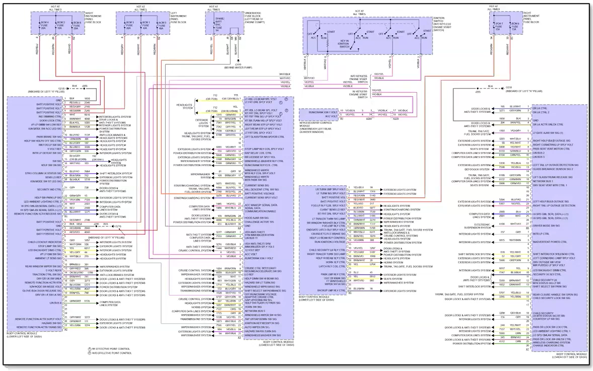
- 126-pin BCM
- Approximately 24 connected systems
Today's BCMs communicate with systems including lighting, door locks, wipers, ABS, charging systems, mirrors, navigation, warning systems and more. The BCM is no longer simply a body controller, it has become one of the most important communication hubs in the vehicle.
Traditional Versus Modern Body Control Systems
Older body electrical systems were relatively simple.
A power window circuit might have:
- Power supply
- Ground
- Relay
- Mechanical switch
- Window motor
Modern systems are very different - A window switch may now have:
- Internal logic circuitry
- Network communication capability
- LIN bus communication
- BCM integration
- Diagnostic capabilities
Diagnosis generally involved checking for voltage, ground and continuity.
Instead of directly controlling a motor, the switch now sends a request across the vehicle network. The BCM evaluates the request and commands the appropriate output.
The result is greater functionality but also increased diagnostic complexity.
Changing the Diagnostic Mindset
Modern body control diagnosis starts with understanding inputs, outputs and data flow rather than chasing wires.
One of the biggest mistakes technicians make is approaching modern body electrical systems like traditional wiring circuits. Modern BCM diagnosis should focus on three questions:
One of the biggest mistakes technicians make is approaching modern body electrical systems like traditional wiring circuits. Modern BCM diagnosis should focus on three questions:
What are the inputs?
Examples include:
What are the outputs?
Examples include:
What processing occurs?
The BCM evaluates incoming information and determines the correct response based on programmed logic.
Every BCM diagnosis can be broken down into three stages: input, processing and output. Understanding which stage has failed is often the fastest path to a correct diagnosis.
Diagnosing BCM Systems Faster with Bi-Directional Controls
Modern scan tools provide a significant advantage because they allow technicians to test both sides of a circuit from the driver's seat.
Verify the Output Side First
Using bi-directional controls (functional tests), command the component directly from the scan tool.
For example:
If the component operates correctly during the functional test, you have already confirmed:
A significant portion of the circuit can be verified in seconds.
Verify the Input Side
Next, examine live data.
Monitor:
If a switch is operated but the BCM never sees the request, the fault can be isolated much more quickly.
This approach allows technicians to identify the problem area before removing trim panels or probing circuits.
Tech Tip
Functional tests and live data effectively split a circuit in half. By confirming outputs first and inputs second, technicians can significantly reduce diagnostic time and avoid unnecessary component replacement.
Why Finding the Right Function Is Often the Biggest Challenge
One of the frustrations that technicians face is simply locating the required function. A common assumption is that similar functions will always be located in the same module across different vehicle manufacturers. That isn't always true.
2022 Volkswagen Taos Example
A battery replacement procedure might logically be expected under:
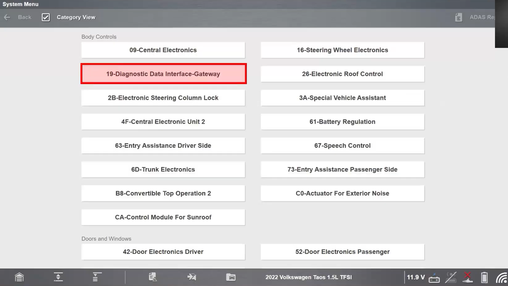
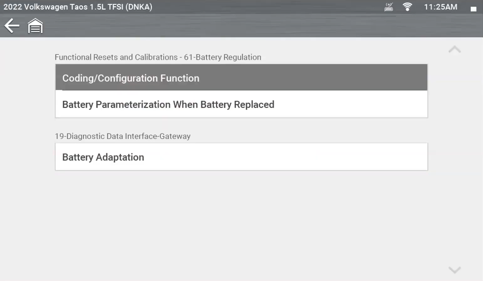
However, the battery adaptation procedure is located within the: Diagnostic Data Interface Gateway. Similarly, Steering Angle Calibration can also be found there rather than within the steering system menus where most technicians would expect to find it.
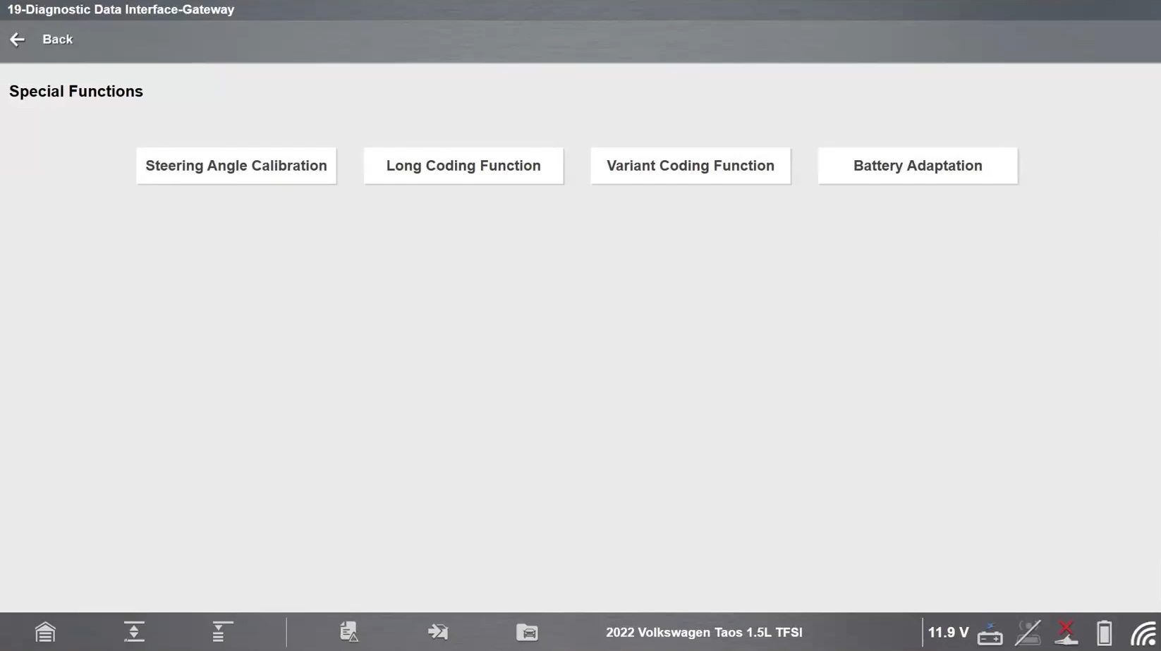
This highlights an important reality of modern vehicles: the challenge isn't always performing the function, sometimes it's simply finding where the OEM chose to place it.
Service Functions, Relearns and Configuration
Many BCM-related repairs don't end when the component has been replaced.
Modern vehicles often require:
Without completing the required procedure, the repair may appear unsuccessful even though the component itself is functioning correctly.
Job-based Service Resets & Relearns help technicians access these procedures quickly without navigating through multiple module menus.
An Exclusive Advantage of Snap-on® Scan Tools with the latest software is the Service Resets and Relearns Functionality (available exclusively for the VERUS Edge, APOLLO, TRITON and ZEUS Series with the latest software).
For the VW Taos Example explained previously you have quick access via the service resets and relearns menu, and here you see listed by job, with the first items listed as the most common maintenance tasks, here you’ll see “Replace Battery”.
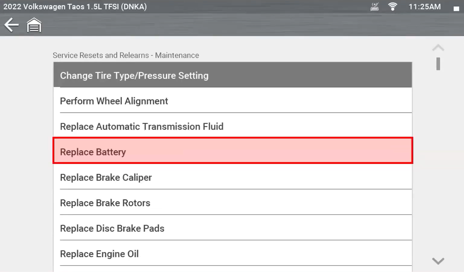
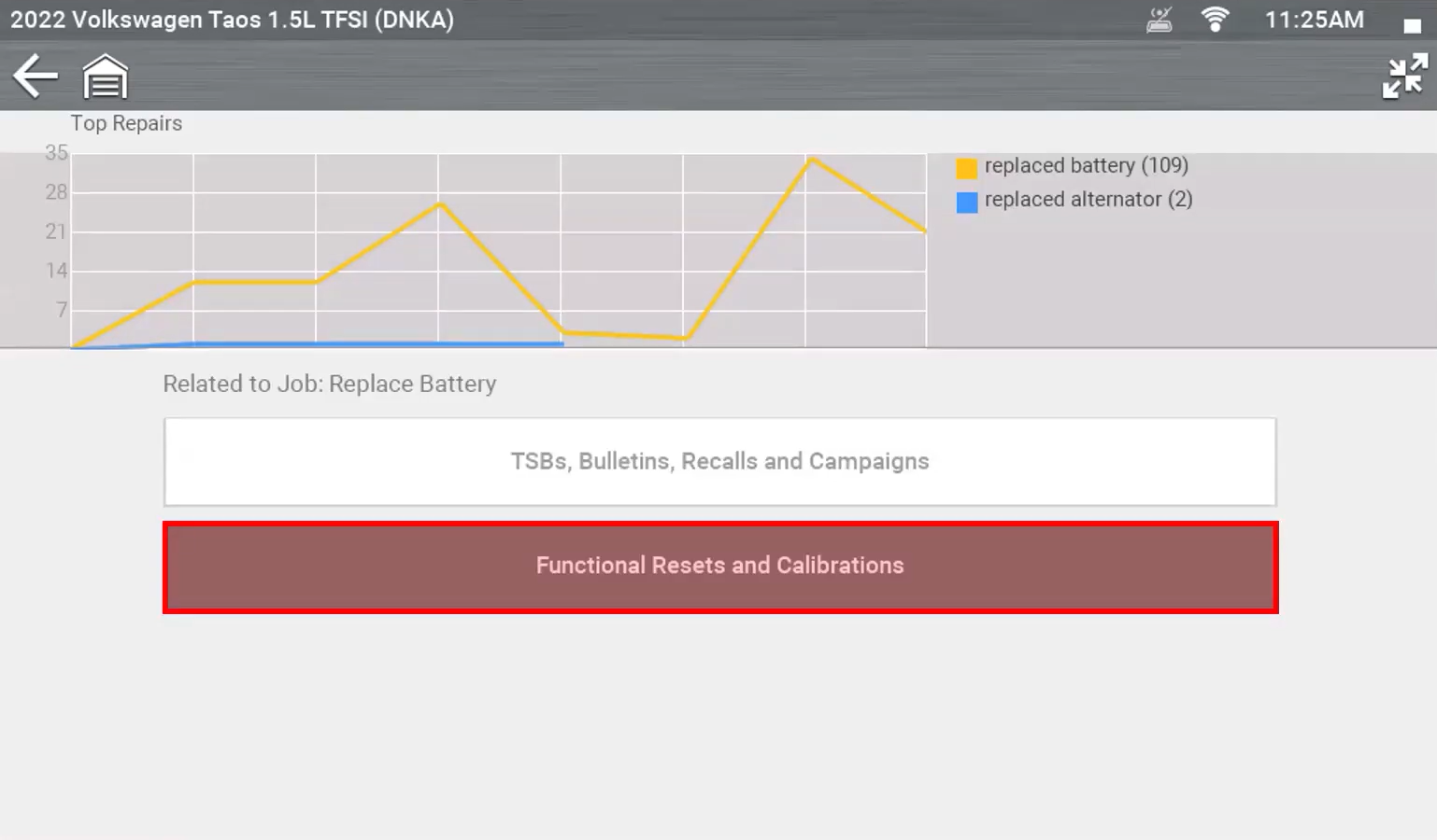
You’ll see a link to “TSBs” as well as “Functional resets and calibrations”, within this menu will display where these functional resets are located , but also gives direct access to the function, preventing you from having to back up menus and navigate to the correct list, saving valuable time and confusion.
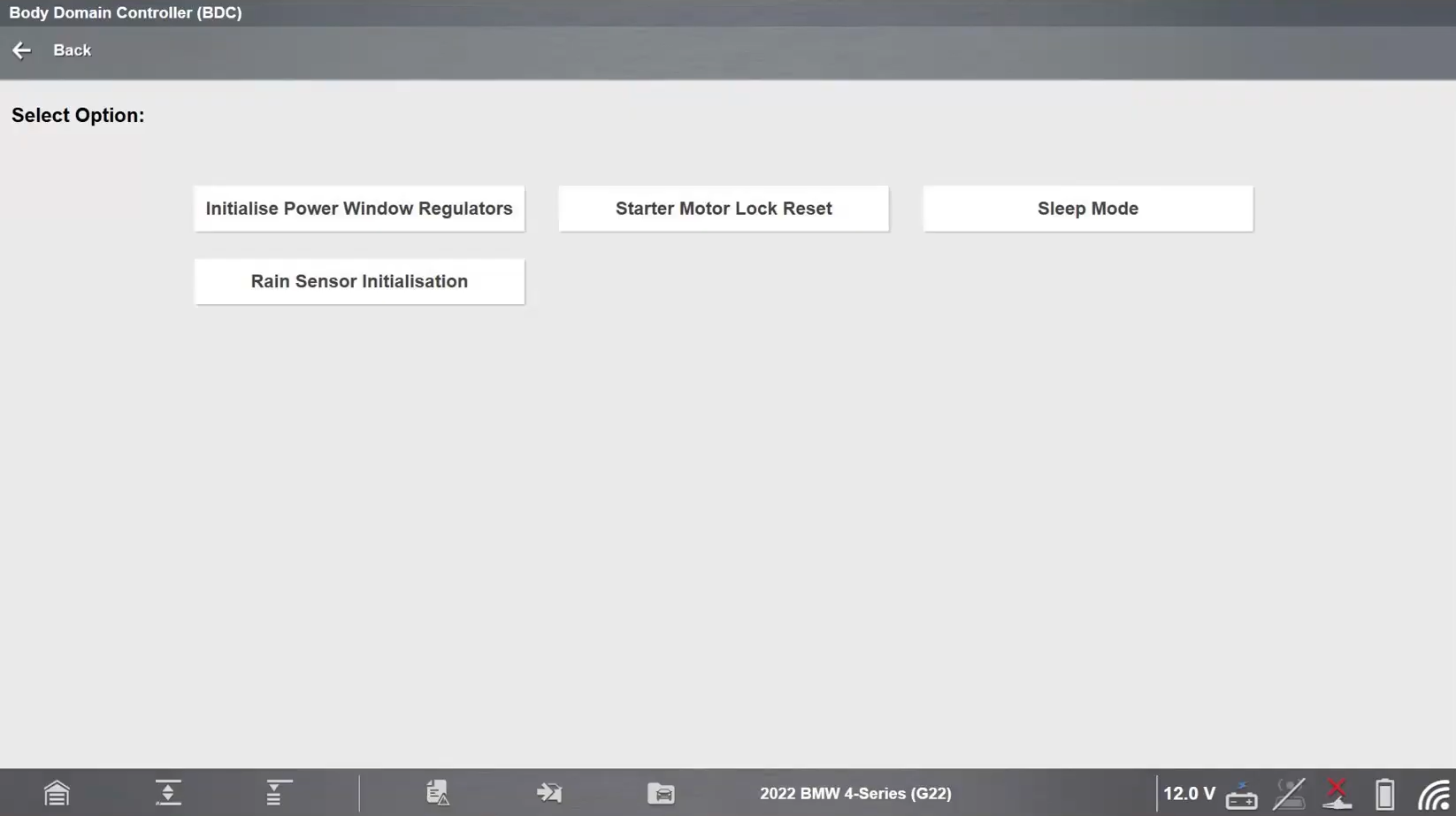
Real-World Example: 2022 BMW 4-Series Parasitic Draw
Many parasitic draw tests require technicians to wait for modules to enter sleep mode naturally. On the 2022 BMW 4-Series, a Sleep Mode function can command modules into sleep state immediately, allowing current draw testing to begin without prolonged waiting. This dramatically reduces setup time and speeds diagnosis.
Real-World Diagnosis: Inputs vs Outputs
Case Study: Jeep® Compass Rear Wiper Diagnosis
The following Jeep Compass example demonstrates how live data and bi-directional controls can quickly isolate whether a fault exists on the input side or output side of a BCM-controlled circuit.
Customer Complaint: Rear wiper inoperative.
At first glance, the fault could involve:
Traditional diagnosis might involve accessing the rear wiper motor, checking powers and grounds, removing trim panels, and tracing wiring through the vehicle.
Begin with a full vehicle pre-scan. Check for:
Even when no codes are present, the scan tool still provides valuable access to functional tests and live data.
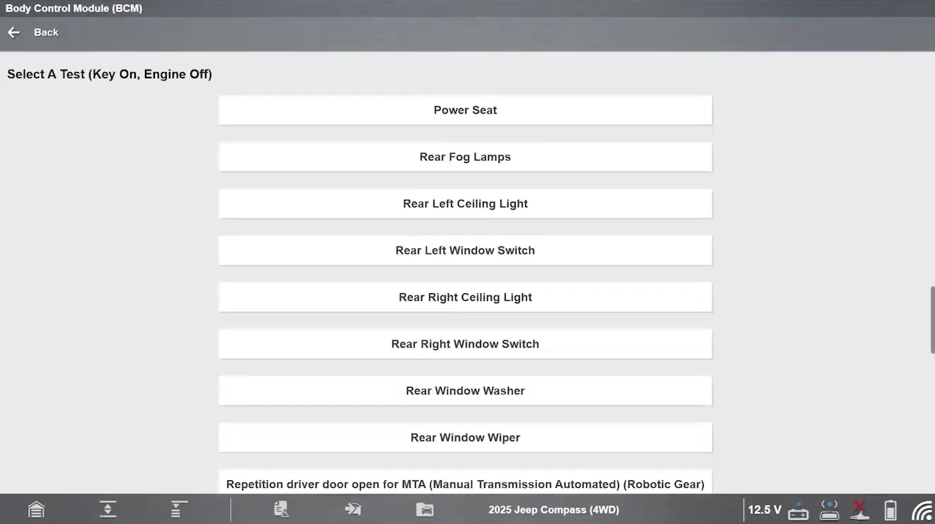
Next Head into Functional Tests
Navigate to: BCM → Functional Tests → Rear Window Wiper
You can command the rear wiper ON and OFF directly from the scan tool.
Using this functional test, several parts of the system can be verified:
Verify the Output Side
Command the rear wiper ON through the functional test. If the rear wiper activates normally, the output side of the circuit is functioning correctly.
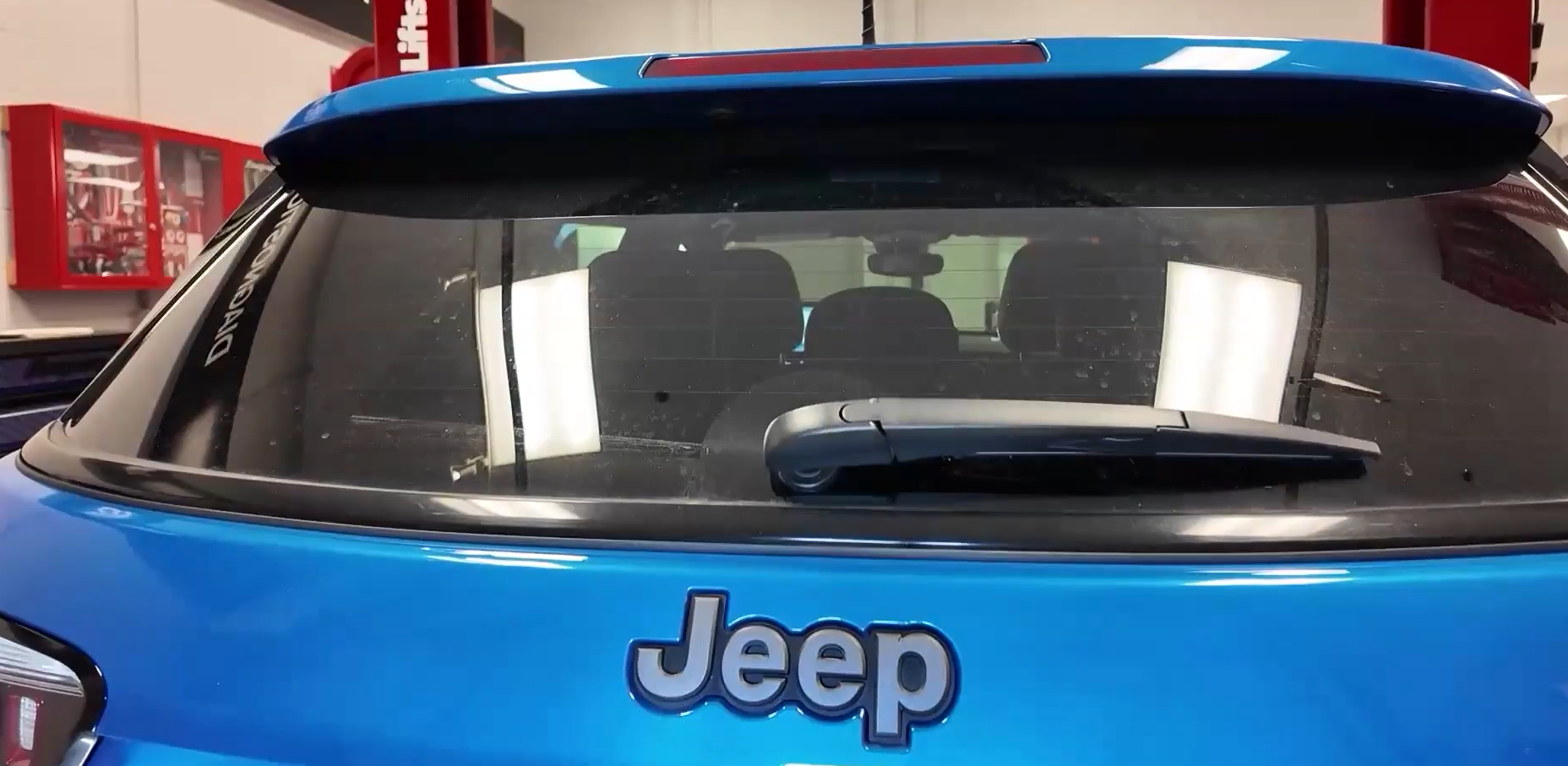
This means there is little reason to:
Verify the Input Side
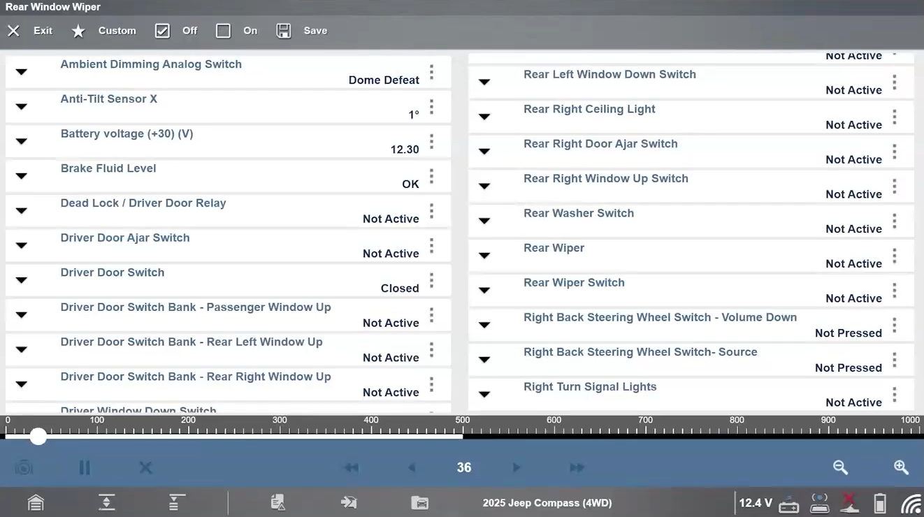
Next, access the BCM data stream. Using a custom data list, monitor:
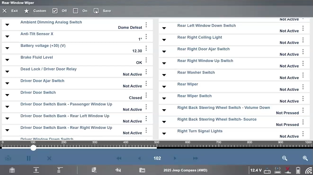
Operate the rear wiper switch while observing the data. Possible outcomes include:
Possible Outcomes
Switch status changes correctly
Switch operated but BCM never sees the request
Potential causes include:
Because the BCM can already operate the rear wiper using the functional test, focus can now shift toward the switch input rather than the motor or output wiring.
Changing the Diagnostic Mindset
Traditional diagnosis often starts by checking motors, wiring and connectors.
A modern BCM diagnostic approach starts with two questions:
Using bidirectional controls and live data allows technicians to quickly separate the input side from the output side of the circuit. This helps pinpoint faults faster, reducing unnecessary disassembly and parts replacement.
Repair Verification
After the repair:
This confirms the BCM is receiving the correct input and commanding the correct output.
Key Takeaway
Modern BCM diagnostics begin with bidirectional controls and live data, not wiring checks. By verifying inputs and outputs first, technicians can isolate faults faster and diagnose with greater confidence.
Fast-Track® Guided Component Tests
Guided Component Tests provide component operation information, test locations, meter connection guidance, known-good values and technician notes directly within the diagnostic workflow. This helps technicians diagnose body electrical faults more accurately and reduces the need to search multiple information sources.
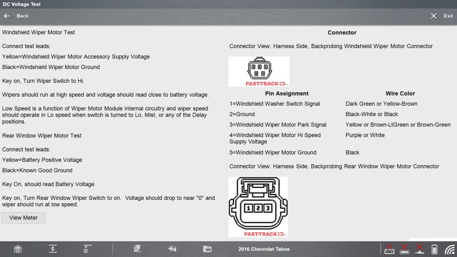
By integrating this information directly into the software, technicians can diagnose body electrical faults with greater confidence. There’s no need to search online, cross-reference multiple manuals or rely on assumption, helping support accurate diagnosis, first-time fixes and reduced risk of vehicle returns.
Smarter BCM Diagnosis for Faster, More Accurate Repairs
Modern Body Control Modules have evolved from simple convenience controllers into sophisticated network management systems responsible for dozens of vehicle functions. Successful BCM diagnosis depends on understanding inputs, outputs and data flow, using live data and bi-directional controls effectively, and completing required service functions after repair. By adopting a scan-tool-led diagnostic strategy, technicians can reduce guesswork, shorten repair times and improve first-time fix rates.
Related BCM Diagnostic Videos
FAQs
1) What does a Body Control Module control?
Depending on the vehicle, a BCM may manage door locks, windows, lighting, wipers, mirrors, security functions, power distribution and other convenience systems.
2) Why are modern BCM systems harder to diagnose?
Many functions are controlled through multiple modules and vehicle networks, requiring technicians to understand data flow as well as traditional electrical diagnosis.
3) Why should functional tests be used early in diagnosis?
Functional tests allow technicians to verify outputs directly from the scan tool, helping isolate faults quickly without extensive disassembly.
4) Why do some repairs require initialization or relearn procedures?
Replacement modules often need configuration, coding or calibration so they can communicate correctly with the rest of the vehicle and support installed vehicle options.
5) What is the fastest way to diagnose BCM-controlled systems?
Use live data and functional tests together. Verify that the BCM receives the correct input and can command the correct output before replacing components or performing extensive wiring checks.
*This article is intended for informational purposes only and is designed to provide general technical insight. It is not intended to serve as step‑by‑step repair or diagnostic instruction. Always follow manufacturer‑approved procedures and safety guidelines when carrying out vehicle diagnostics or repairs.