By Damien Coleman
This month’s Technical Focus article shows that a systematic approach to fault-finding can help the technician get to the bottom of a problem quicker...
Many modern systems, such as common rail diesel injection, can appear to be so complex that they seem to operate by magic.
As a vehicle technician you can be presented with a seemingly endless amount of data relating to fuel pressure feedback, fuel pressure control, cam/crank synchronisation, measured mass airflow, injector flow correction feedback, and many other areas.
However, if you prepare yourself with a fundamental understanding of the system and all data available about the fault, a systematic approach to the fault-finding procedure can be carried out.
Below is a table showing the live data returned from a common rail diesel injection vehicle with an EDC16 engine management system:
|
Data Parameter
|
Value Returned
|
|
Engine speed
|
1600 RPM
|
|
Camshaft/crankshaft synchronisation
|
Yes
|
|
Measured fuel pressure
|
280 Bar
|
|
Fuel pressure measure/desired loop difference
|
20 Bar
|
|
Fuel inlet metering valve duty cycle
|
17%
|
|
Injector flow correction cylinder 1
|
1.35 mm3/stroke
|
|
Injector flow correction cylinder 2
|
-1.26 mm3/stroke
|
|
Injector flow correction cylinder 3
|
1.05 mm3/stroke
|
|
Injector flow correction cylinder 4
|
-1.69 mm3/stroke
|
There is an enormous amount of data available from these data parameters, which can allow you to ascertain the nature of the fault.
The actual operation of the fuel system can be compared to the desired system operation and using the data, a decision can be made on the condition of the system and where a fault (if any) may be.
An oscilloscope is another important tool when investigating a fault with such a complex system.
Below is an oscilloscope waveform from an Audi with the 2.0L common rail engine.
The yellow trace is the fuel rail pressure sensor voltage (feedback) and the green trace is the current flow through the inlet metering valve (command). The waveform was captured during a wide open throttle (WOT) condition.
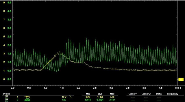
This image alone tells us that the fuel inlet metering valve is a normally open valve.
The engine control module (ECM) decreases the duty cycle when the required fuel pressure is increased. This allows less current to flow through the solenoid and the valve is allowed to open, which increases the fuel pressure measured at the fuel rail.
When the fuel pressure demand decreases, the duty cycle control from the ECM increases.
This allows more current to flow through the solenoid which results in a reduction of the fuel pressure. Duty cycle is often referred to as pulse width modulation (PWM) control.
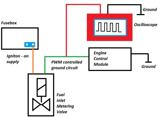
The duty cycle control on the ground side of the fuel inlet metering valve can be analysed using an oscilloscope.
The waveform below displays the fuel rail pressure feedback voltage (yellow trace) and the fuel inlet metering valve duty cycle control from the ECM (green trace).
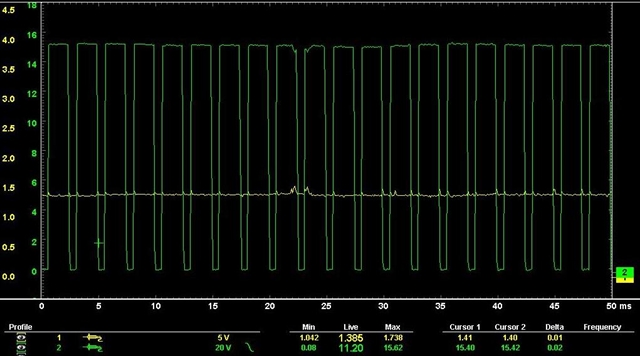
The oscilloscope is connected to the control wire for the fuel inlet metering valve. You must be mindful that this is the ground control circuit. System voltage on this wire indicates open circuit voltage.
By careful analysis using serial (scan-tool) and parallel (oscilloscope) diagnostics you will now be in a position to identify the area of concern accurately and in a timely manner.
The final word should be left to William Thomson (Lord Kelvin), whose quote is an apt synopsis for this article:
“When you can measure what you are speaking about and express it in numbers, you know something about it, but when you cannot measure it, when you cannot express it in terms of numbers, your knowledge is of a meagre and unsatisfactory kind.”
Date posted: 24 June 2016