In the second part of an examination of motor control systems, Damien Coleman looks at methods to present accurate control of the system…
The polarity of a motor is reversible, which allows for accurate control of the entire system. One way to control the polarity is by designing what is known as an “H-drive” bridge circuit.
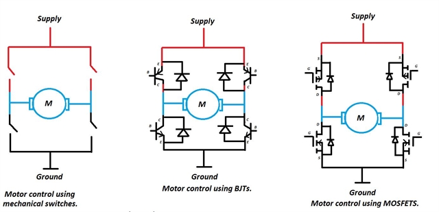
The bridge circuit can be created using mechanical switches, bipolar junction transistors (BJTs) or metal oxide field effect transistors (MOSFETs). MOFSETs are the most common way of controlling such a circuit.
The diagram below gives an overview of all three systems:
Below are two images which demonstrate the fundamental operation of the circuit, simplified with basic mechanical switches:
With switches S1 and S4 closed, the current flow through the motor results in the motor rotating in a clockwise rotation. With S2 and S3 closed the current flow through the motor results in the motor rotating in an anti-clockwise direction.
If S1 and S2, or S3 and S4, are closed simultaneously then the motor will be shorted-circuited and the circuit may be damaged.
Feedback and Control
The engine control module uses the feedback from the accelerator pedal position sensor to determine driver demand, as outlined in my previous article.
Vehicle demands may also exist in the form of a traction control system command or from the engine speed limiter. However for correct operation of the electronic throttle control motor a closed loop control system must be implemented using throttle position sensors.
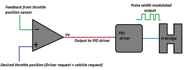
In this simplified example above, an operational amplifier voltage comparator uses inputs from both the desired throttle position and actual throttle position.
The output (Vo) from the comparator is the voltage difference between both signal voltages applied. This output voltage is used to control a PID (proportional, integral, derivative) driver which then outputs a PWM (pulse width modulated) control to the H drive circuit.
Date posted: 12 October 2016