This article describes to technicians how a relatively simple fault became slightly more complicated to rectify when a component with different operating parameters was fitted. Damien Coleman will guide you through how to resolve the issue quickly and effectively by further investigation and testing, using a TRITON-D8.
A 2010 Volkswagen Polo with a 1.6 litre common rail diesel injection engine (engine code - CAYC), was reported to have an engine management light and glow plug warning light both illuminated. A diagnostic scan tool was connected to the vehicle’s data link connector and the following error code was stored in the electronic control module:
P2455 – Diesel particulate filter pressure sensor, short to positive or open circuit.
This fault code can be caused by several factors, which are listed below:
- Short circuit in the wiring between the sensor supply voltage (5 volts) and the signal wire
- Open circuit on the ground circuit of the sensor
- Faulty exhaust gas differential pressure sensor
A voltmeter was connected to the signal wire of the sensor and a voltage of 4.9 volts was measured.

Diagram 1: Component pin assignment:
Pin 1: 5 Volt supply
Pin 2: Ground
Pin 3: Signal output
The simplified diagram above shows the circuit layout. The signal wire (pin 3) has a voltage of ≈5 volts applied to the sensor signal circuit from the engine control module. The sensor is a piezoresistive measuring cell with integrated evaluation electronics.
When the differential pressure is low, the voltage is ‘pulled’ closer to ground potential. As the differential pressure across the filter increases, the output voltage increases proportionally. The engine control module uses this voltage signal to determine the soot loading of the diesel particulate filter.
Increased soot loading will cause an increase in exhaust gas pressure upstream of the filter. This is referred to as 'closed-loop monitoring'.
As we can see from the fault code, several electrical tests must be conducted to pinpoint the actual fault. After the initial voltage test at the sensor signal wire (4.9 volts), the next test was to validate the ground circuit. The ground for the differential pressure sensor is shared with the turbocharger boost pressure sensor and the transmission neutral position sensor, so a fault here was highly unlikely as there were no other fault codes stored in the Engine ECM. However, the circuit was tested and proved to be in good condition. The wiring was also tested for a short circuit between the supply and signal wires which, no fault was found here either.
This proved the fault was within the DPF pressure sensor.
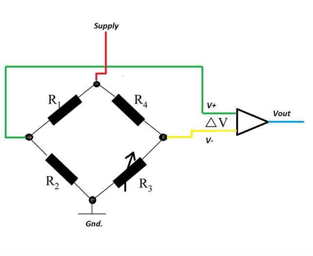
Diagram 2: Sensor construction
The diagram above illustrates a simplified sensor layout, with a piezoresistive bridge circuit connected to an operational amplifier. The bridge is two series of circuits connected in parallel. Normally three resistors within the bridge circuit will have the same resistance value with one resistor having a variable resistance. With zero pressure applied to the circuit, all resistance values are equal so the output from the operational amplifier is zero (V+ = V-). When a pressure change occurs in the sensor, the bridge will become unbalanced and a voltage will be output (Vout) to the sensor evaluation circuit.
A new sensor was sourced and fitted. A voltmeter connected to the signal wire displayed 0.5 volts with the key on, engine off. With the engine idling, the voltage remained at 0.5 volts and on a road test, increased to 0.9 volts under wide-open throttle; a new fault was now present in the engine management system:
P2453 - Diesel particulate filter pressure sensor, signal implausible
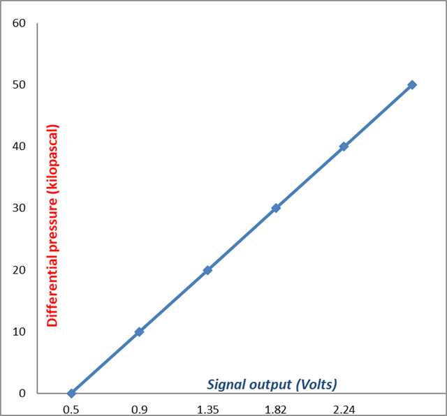
The graph below outlines the normal expected voltage output with respect to exhaust gas differential pressure:
This code would initially clear but would return once the ignition key was cycled (key on, engine off). This was an indication that the engine control module detected an error with the signal voltage under this condition. Any mechanical faults could be ruled out, as the engine did not need to be running for the fault code to return.
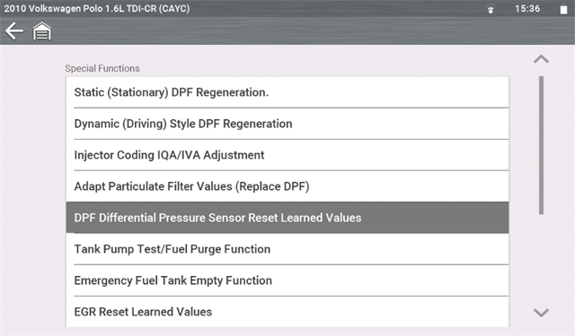
A basic setting for the DPF sensor was carried out using a diagnostic scan tool, however, this procedure failed.
The next step in the diagnostic process was to manipulate the signal output voltage using a potentiometer. The voltage was altered in steps of 100 millivolts and the trouble code was erased at each increment. The trouble code returned each time until a voltage of 1 volt was reached. The code would not return when the ignition was cycled. This indicated the expected key on, engine off voltage from the sensor.
Further investigation into the part supplied was carried out and the issue was found with the supplier of the part. Although the part was ordered from the vehicle identification number, there was a different part number supplied. This can be a normal procedure as parts can often be superseded.
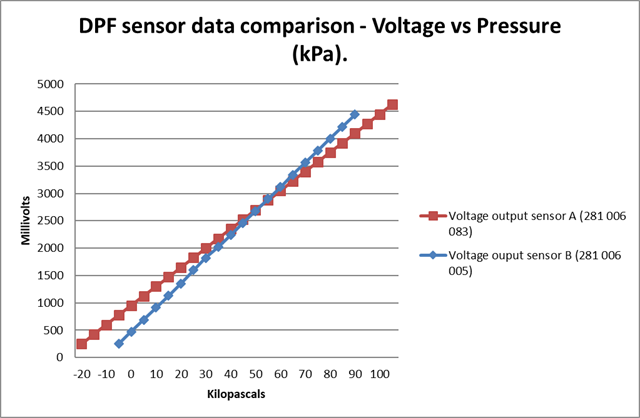
It was later found that the part supplied for vehicles fitted with a Siemens engine control module, was part number 281 006 005. The sensor originally fitted to the vehicle was part number 281 006 083, and these sensors are fitted to engines with a continental engine control module.
With the incorrect sensor fitted, the engine control module interpreted the signal voltage as a pressure of – 15 kPa, hence the implausibility fault code. The graph below outlines the difference in voltage output between both pressure sensors.
The fault code was cleared and the vehicle preformed as expected with the correct DPF Pressure sensor fitted.