System operation:
The diagram below shows the electrical operation of the turbocharger. The diagram illustrates the “Command” and “Feedback” part of the circuit. The Turbo Boost Control Solenoid has a constant supply (System Voltage) from the Engine Bay Fusebox and is controlled on the ground side by the Engine Control Module.
Closed loop control is via the Turbo Boost Pressure Sensor. This component has a constant 5 volt supply and ground from the engine control module (ECM). The signal wire has a 5 volt biased voltage from the engine control module that is manipulated by an integrated circuit, within the sensor, to vary the output voltage depending on pressure measured at the sensor.
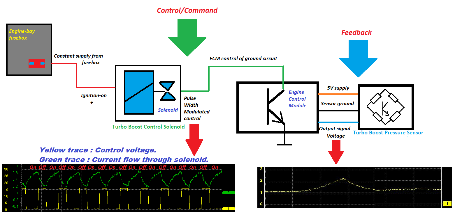
The waveforms below the system layout show the voltage control (ground side) and current flow through the solenoid. This will be expanded upon later in the article. The image on the right shows the volatge from the boost pressure sensor under snap throttle conditions.
Performing a Solenoid Valve Test
Visual Inspection:
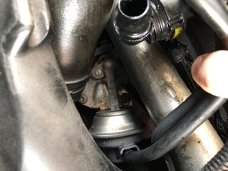
An initial visual inspection can be used to observe the wastegate actuator on engine start-up. The image below shows the rod fully extended with the key on, engine off. This is the minimum boost position. Should the electrical or pneumatic system fail, the turbochrger will return to this position to protect the engine from an overboost condition.
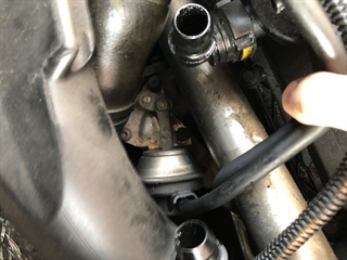
When the engine starts, a vacuum is created by the engine vacuum pump. The boost pressure control solenoid is actuated by the ECM which closes the wastegate to allow the turbocharger to generate boost. It must be noted that the pressure in the ntake manifold will equal athmospheric pressure at idle. As the engine speed increases the turbocharger Turbine will increase in speed due to greater exhaust gas flow. The impeller will also increase in speed to pressurise the air in the intake manifold. The turbine and impeller wheels are connected via a common shaft.
Key on, engine off:
Key on, Engine running (idle):
Live data will display absolute pressure as opposed to gauge pressure. See example below:
|
Data Parameter
|
Idle
|
Wide Open Throttle
|
|
Intake Manifold Pressure
|
1020 mBar
|
2210 mBar
|
|
Barometric Pressure
|
1013 mBar
|
1013 mBar
|
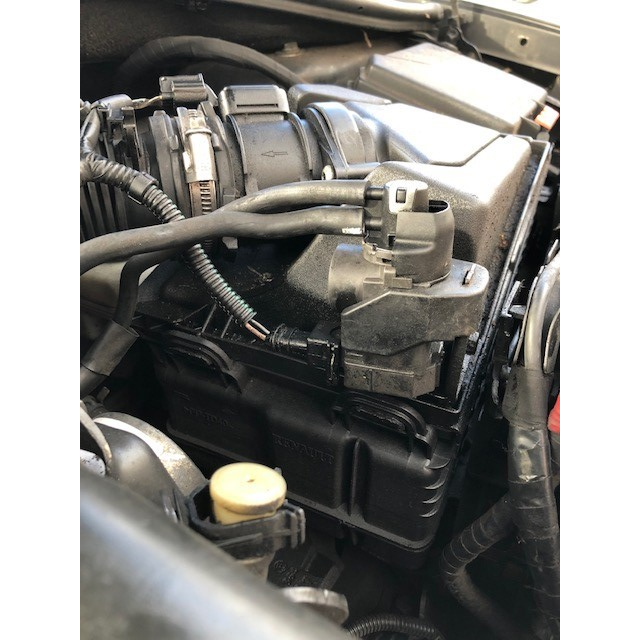
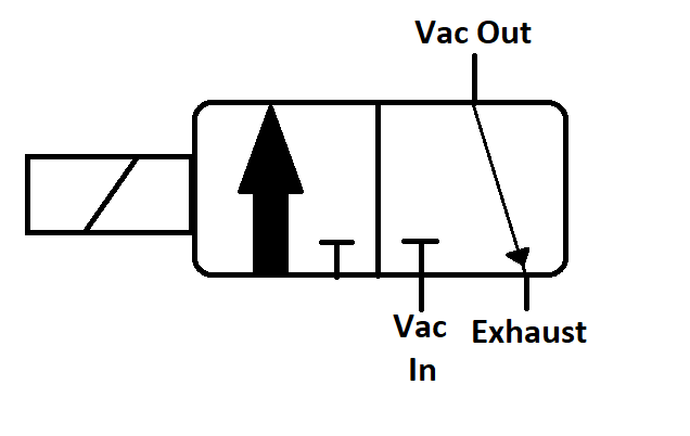
Turbo boost control solenoid valve:
The solenoid valve used to control the turbocharger is a three way, normally closed valve. There are three ports, although only two may be easily identifiable. There will be a supply (Vac-In) from the vacuum pump, output to the turbocharger (Vac-Out) and an exhaust, which can sometimes be connected to the intake air filter housing. The purpose of the exhaust is to bleed atmospheric air pressure into the vacuum circuit to open the wastegate and control the boost pressure.
Turbo boost control solenoid valve
3 Way, normally closed valve
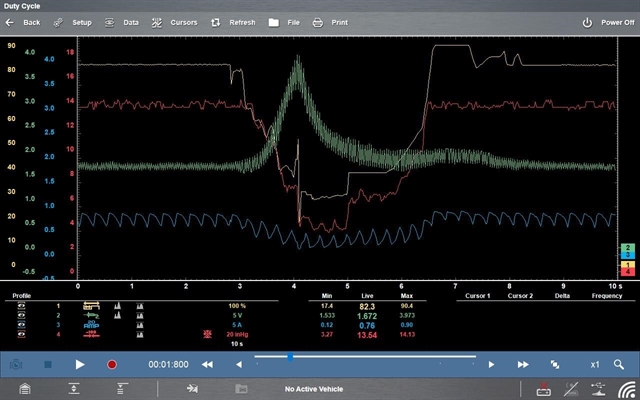
Waveforms:
The waveform below shows both the electrical and pneumatic operation of the solenoid valve upon engine start-up. A pressure transducer was connected between the solenoid valve and the turbocharger to sample the actual vacuum.
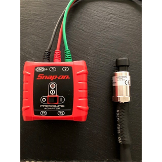
Pressure Transducer 0-100 PSI (6.9 Bar)
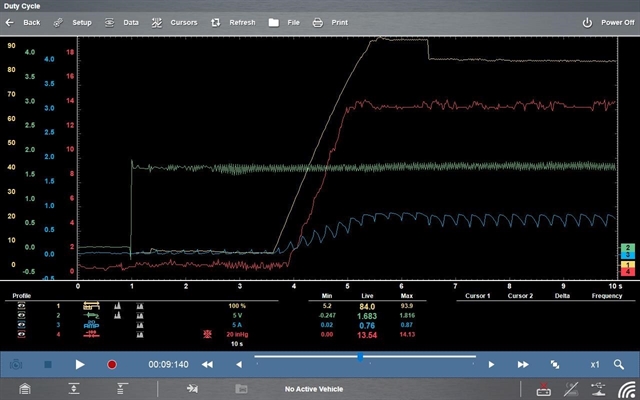
Engine start-up
-
Green Channel – Boost Pressure Solenoid Voltage.
-
Blue Channel – Solenoid Valve Current Flow.
-
Red Channel – Actual Vacuum.
The waveform above shows the duty cycle control of the solenoid valve increase to 90% when the engine starts, this results in a current flow of 0.87 amps and a vacuum of 13.5 inches of mercury (460 mBar) applied to the turbocharger actuator. The voltage on the boost pressure sensor signal wire is 1.6 volts at zero boost pressure.
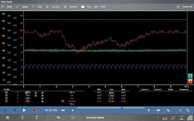
Brake pedal depressed
In the image above, we can see the vacuum deplete and increase after several applications of the brake pedal. The brake servo requires a large vacuum to operate and this can affect the overall vacuum system, however, a good vacuum pump can re-instate the required vacuum quickly.
Wide open throttle
The image above shows the sytsem under Wide Open Throttle conditions. As the boost pressure increases, the duty cycle control of the solenoid valve is reduced which causes the vacuum applied to the turbocharger actuator to reduce. Once the boost pressure stabilises after Over-run the Duty Cycle again increases.
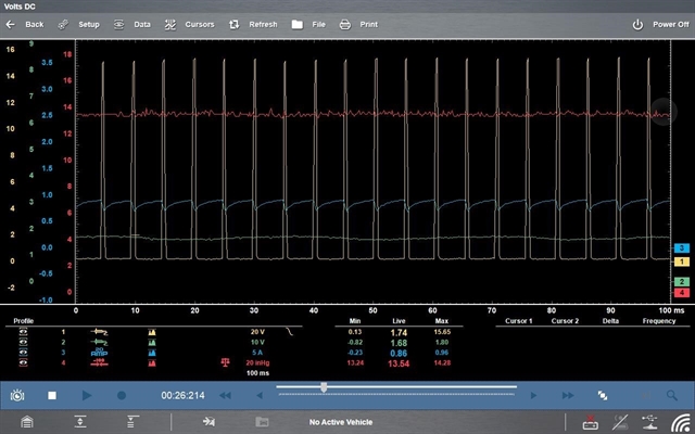
Boost pressure controlsolenoid control at idle
The image above shows the Duty Cycle control of the solenoid. As the solenoid is supplied (electrically) with a constant supply, the current flow is controlled by varying the duty cycle on the ground side of the actuator. The current flow (blue trace) increases when the voltage on the ground side (yellow trace) is 0 volts. As the ground circuit is opened the current flow decreases. The duty cycle can be estimated by looking at the average voltage on the ground circuit and comparing it to the applied voltage. A lower voltage means a larger duty cycle.