Before starting this process, ensure that:
• The bodywork has no obvious damage
• That the workshop lighting is not excessively bright and that there is no glare around the calibration area
• That the vehicle has a full tank of fuel
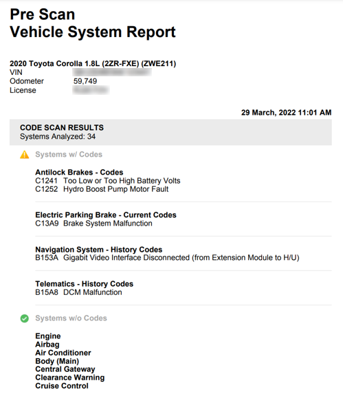
To start, you will need to conduct a pre-scan using your Snap-on tool to identify any stored codes and repair any faults prior to the calibration.
When this is done, you can now start the calibration.
First, find the vehicle's ‘centre line’. There are videos on the EZ-ADAS app that will give you step-by-step instructions on how to do this.

After finding the front centre line, you need to find the rear centre line.
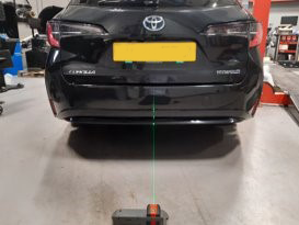
Now it’s time to line them both together. Lining up the rear lazer to the white AS11 alignment plate, to establish the true vehicle's centre line.
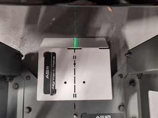
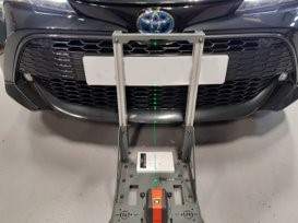
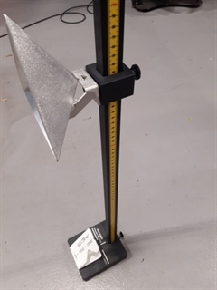
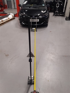
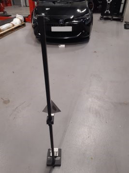
Following the EZ-ADAS App, Using the RAD-10 which is a universal device, use the measurements specific to the Toyota Carolla putting the front cone into place so that the front radar can identify the target.
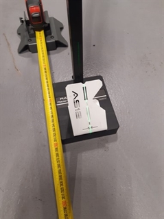
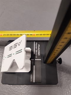
Metallic objects may affect the radar’s signal during calibration, so please ensure no metallic objects are in the radar’s calibration area leaving the target stand in place.
Please note: the AS11 and AS12 laser guides were removed after taking the photo.
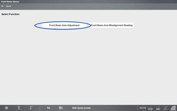
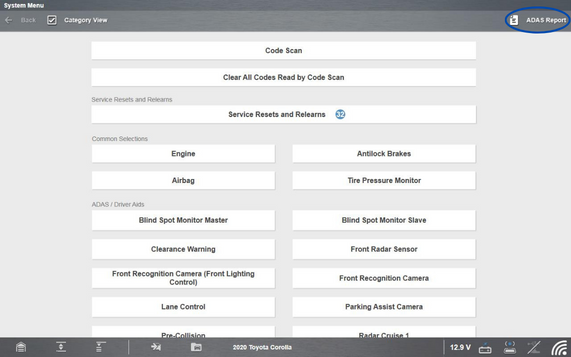
Go back to your Snap-on scan tool (having previously carried out a code scan) and select ‘Front Radar Sensor’.
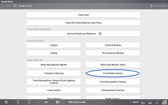
Select 'Functional Tests'
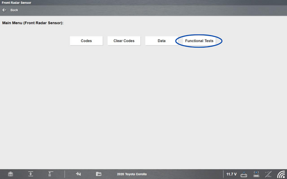
Select 'Front Beam Axis Adjustment'
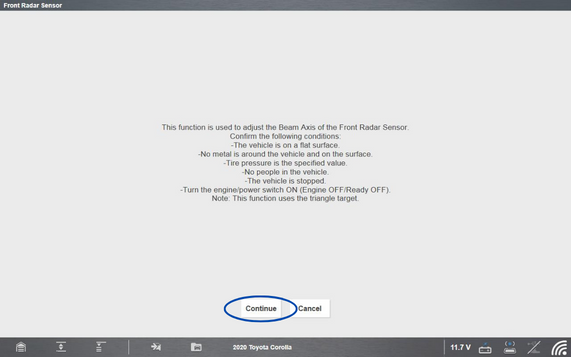
Select 'Continue'
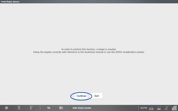
Select 'Continue' again
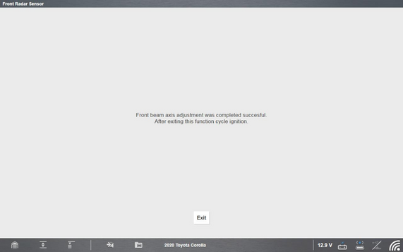
Time to wait!
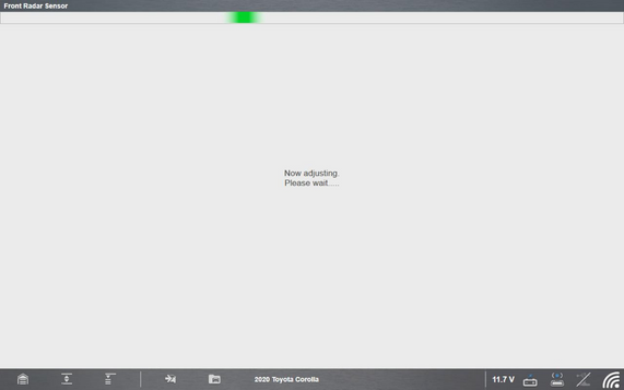
The calibration is now complete.
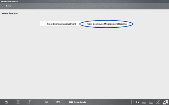
Now it's time to grab a 'Front Beam Axis Misalignment Reading'. This is to checks the measurements adhere to the OE's guidelines. OE guidelines state in this instance that the horizontal and vertical degrees should be set at 0 degree – with a +/- 0.5 degree tolerance.
To begin, select 'Front Beam Axis Misalignment Reading'
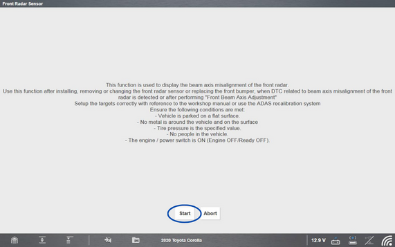
Click 'Start'
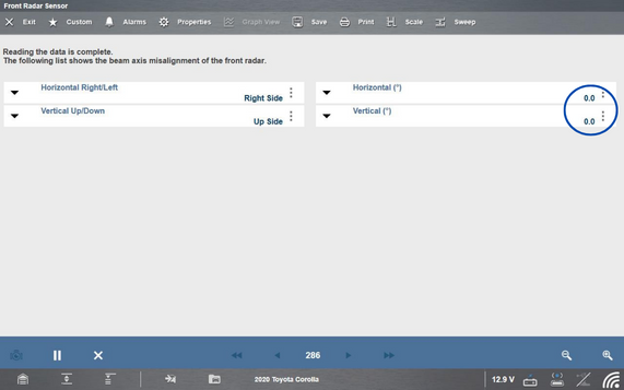
The horzizontal and vertical measurements should show 0. This is circled in the image below.
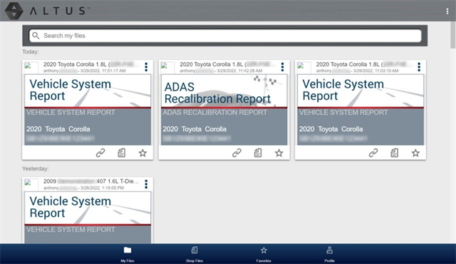
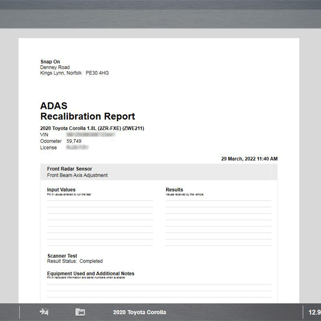
Once completed, you will have the option to save the ADAS report. To do this, exit the radar module on your Snap-on scan tool and select 'ADAS Report' in the top right hand corner. The Snap-on Cloud can be used for saving/printing and e-mailing customer records. This is particularly useful for BodyShops doing insurance work, as this ADAS report along with the pre and post-scan can be used to send to the insurance company in order to get paid for the repair.
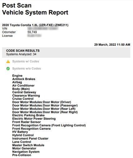
Now it’s time to do a road test to:
- Verify operation and post-scan.
- Clear all trouble codes stored
- And carry out in initial post-scan to ensure no unwanted codes are still stored.