Modern vehicles rely on high‑speed electronic signals and adaptive control strategies to operate correctly. While scan tools provide valuable direction, they only show how a control module is interpreting information after processing.
Scanner data often reflects the effect of a problem rather than the root cause. Signals are sampled, filtered, and compared against software thresholds before being displayed. During that process, brief dropouts, distortion, or intermittent failures can be hidden.
Using Snap-on® Fast-Track® Guided Component Tests to Diagnose and Repair with Confidence
Front Door Versus Back Door Data
Think of the control module like a building with a front door and a back door.
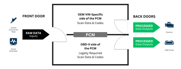
The front door is where raw signal data enters the module directly from sensors and actuators. This is the signal before any processing, filtering, or decision making occurs. The back door is where processed data exits the module, after software logic, fault thresholds, and calculations have already been applied.
Scan tools view information at the back door - what the module thinks is happening based on its programming. Scope testing allows technicians to access the signal at the front door, directly at the component, before the module has had a chance to alter or interpret it. Seeing both the front door and back door is essential to identifying the true cause of a failure.
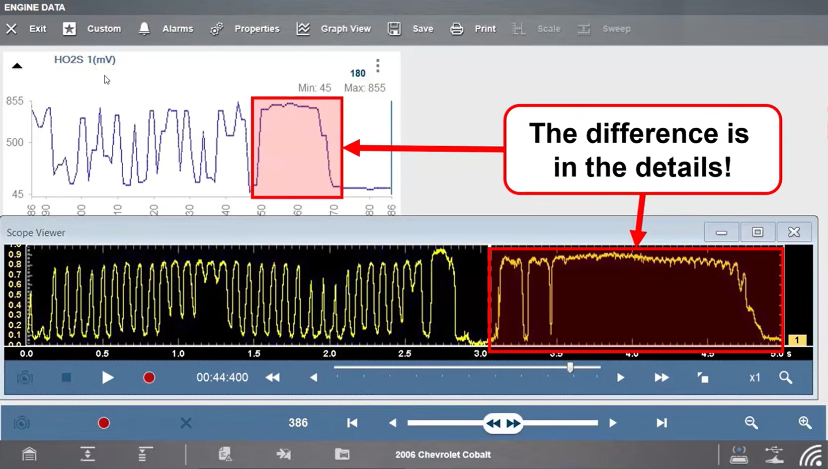
Scope data tells a different story.
Scope data captures the signal directly at the component in real time, before any module processing occurs. This preserved signal detail allows technicians to see exactly what a component is doing as the event happens. Understanding the difference between front door and back door data is critical when diagnosing modern electrical and electronic systems using a test‑don’t‑guess approach.
Why Component Testing Matters
Intermittent electrical faults and processed scan data are among the leading causes of misdiagnosis and unnecessary parts replacement.
Diagnostic trouble codes are only set when software thresholds are exceeded. Many intermittent failures never cross those thresholds, especially on the OEM control side, allowing components to fail without setting a code.
Snap-on Fast-Track® Guided Component Tests pair scope based signal verification with clear setup instructions and known good waveform comparisons, allowing technicians to confirm component operation rather than relying on assumptions. This closes the gap between symptom and root cause and helps reduce repeat repairs.
Understanding Component Failures
Most electrical component failures fall into three primary categories:
• Open circuits prevent voltage or current from reaching its destination
• Short circuits alter the intended signal or current path
• Resistance related faults restrict current flow even when voltage appears normal
Many of these failures can still show normal voltage or continuity during basic checks. Without testing the component under operating conditions, the fault may remain hidden until the problem returns.
Identifying which type of failure is present early in the diagnostic process helps technicians choose the correct test and avoid unnecessary component replacement.
How Fast-Track® Guided Component Tests Help
Fast-Track® Guided Component Tests are designed to remove guesswork from component testing by leading technicians through proper setup and execution.
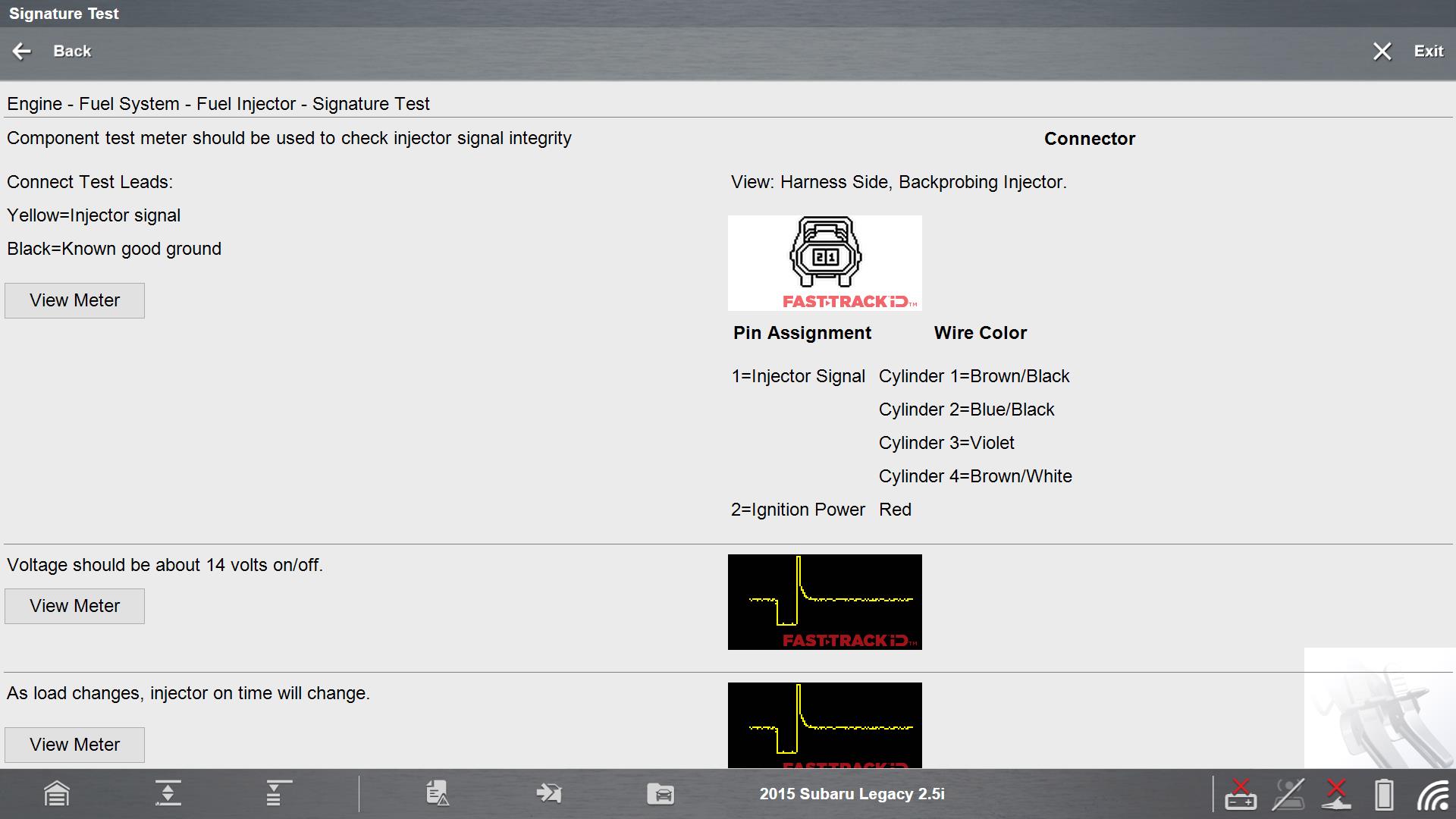
Guided component tests help technicians test and verify component operation by providing:
• Operations
• Location of the component
• Clear connector views and wiring pinouts
• Tech notes
• 1-6 testing methods
• Step by step test setup instructions on how to hookup , how to test, and known-good and bad results
This helps technicians:
• Avoid unnecessary parts replacements
• Prevents comebacks
• Prevents loss of a customer (never come back)
• Attract new customers
• Increase shop profitability
Fast-Track® Guided Component Tests provide the information technicians typically have to search for or guess at: component location, operating principles, wiring pinouts, correct test method, and what a good signal should look like.
Automatic scope configuration ensures the correct scale and sweep are applied, allowing technicians to focus on diagnosis rather than tool setup. Visual confirmation makes it easier to determine whether a component is operating normally or failing electrically. Built-in training content allows technicians of any experience level to understand how a system works, how to test it, and how to interpret results without leaving the tool.
VVT Position Sensor Signature Test
BMW VANOS System Overview
BMW variable valve timing (VVT), known as VANOS (Variable Nockenwellen Steuerung), dynamically adjusts camshaft timing using oil pressure and electronic control.
Key system components include:
• Engine oil and oil pump
• VANOS solenoids
• Camshaft gears
• VVT position sensors
• Digital motor electronics (DME)
Because VANOS depends on oil pressure, technicians commonly assume oil condition is the root cause of VVT faults. While oil issues are common, electrical failures in sensors or solenoids can create identical symptoms and should be tested early.
Common VVT Related Diagnostic Trouble Codes
• P0010
• P0012
• P0013
• P0015
Why the VVT Signature Test Matters
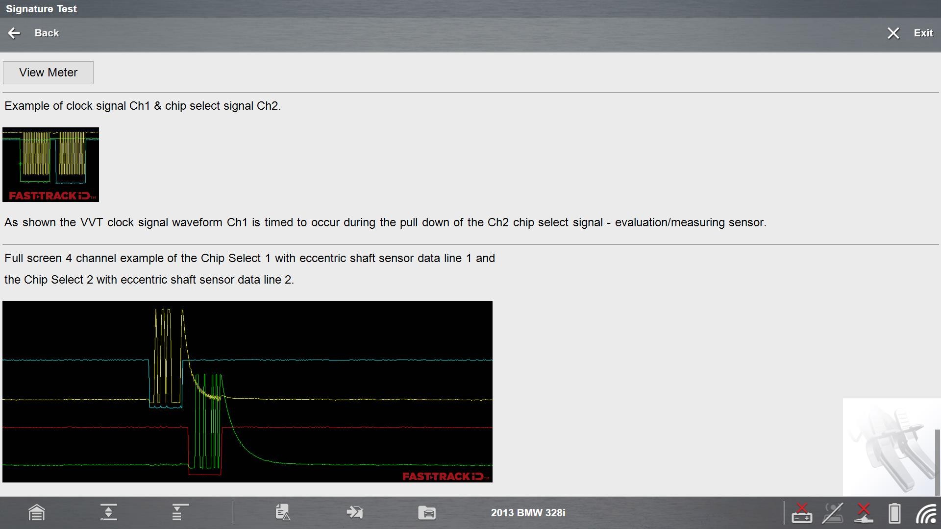
The VVT position sensor signature test allows technicians to evaluate sensor performance using waveform shape and timing, not just voltage value.
This test:
• Confirms sensor operation in real time
• Reveals intermittent signal dropouts
• Allows direct comparison with known‑good patterns
• Helps verify camshaft correlation
When diagnosing VVT concerns, technicians will often check oil condition first, followed by inspection of the solenoids. Guided component tests make it easier to test VVT solenoids electrically, helping verify operation before condemning mechanical components.
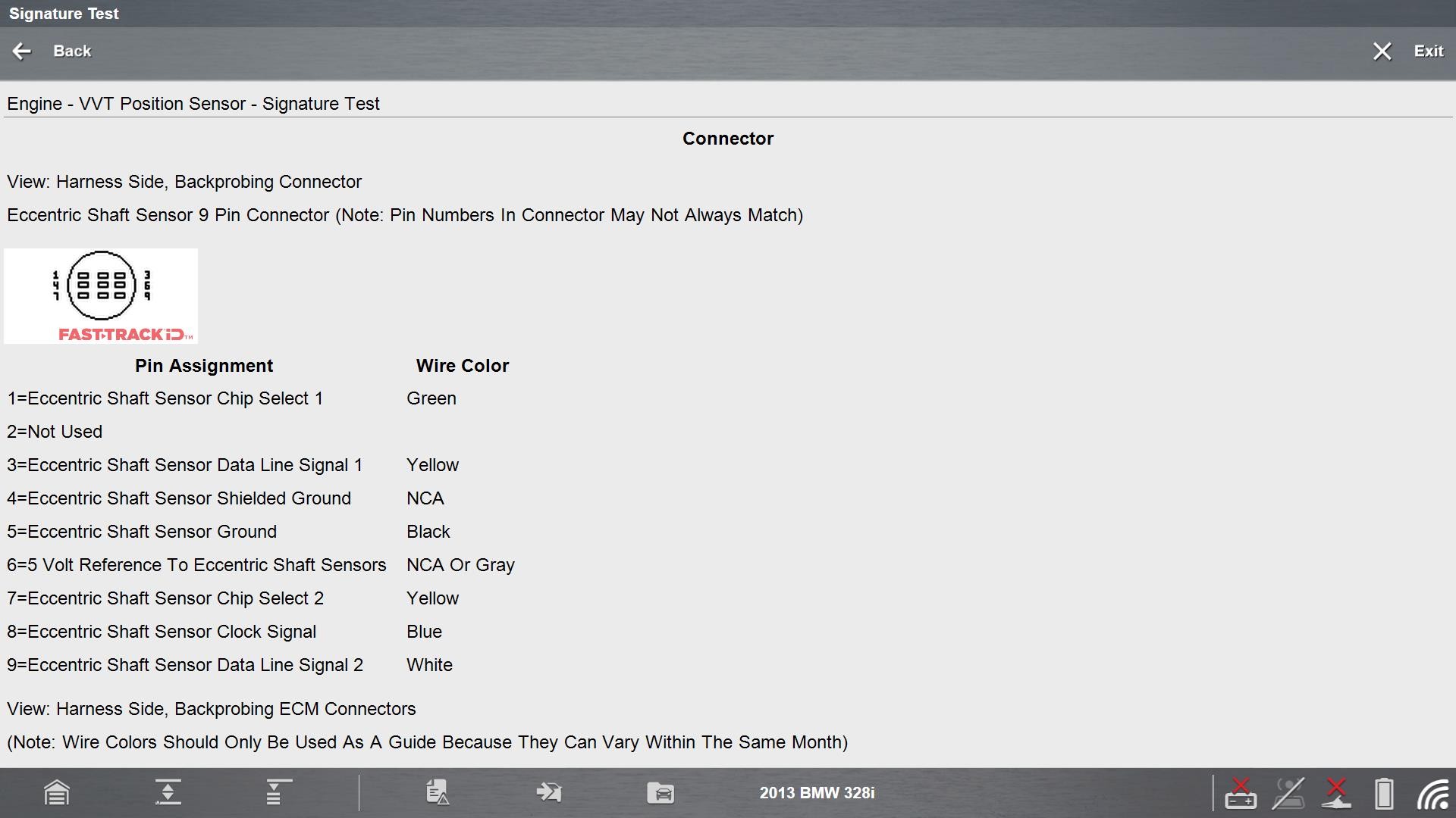
Snap-on Fast-Track® Guided Component Tests walks technicians through:
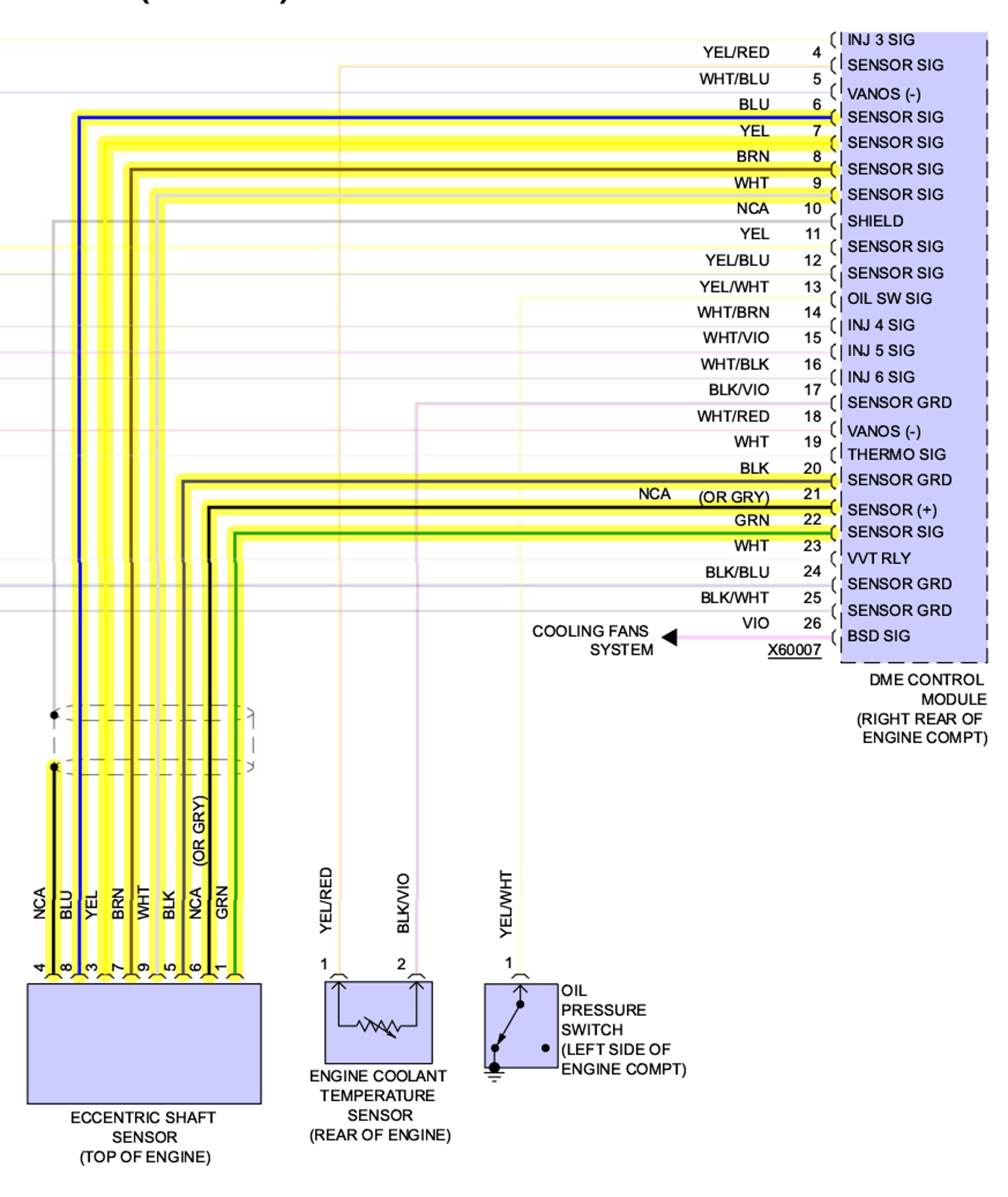
• Sensor location and connector views
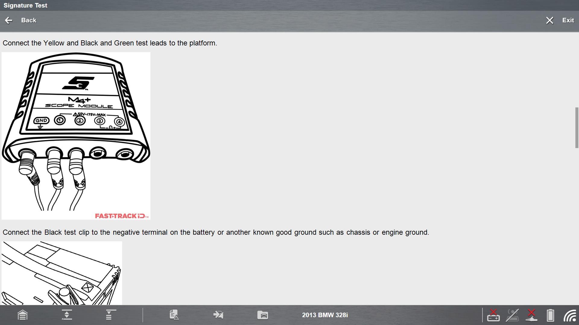
• Proper scope connections
• Automatic scope setup for scale and sweep
• Known good waveform references
Technicians connect directly at the sensor connector and view live waveforms while the engine is running.
Full Color Waveform Analysis
The updated VVT Guided Component Test includes five new full color waveform images, covering:
• Intake camshaft sensor signatures
• Exhaust camshaft sensor signatures
• Known good waveform overlays
• Multi channel camshaft correlation
• RPM dependent frequency changes
Small deviations in waveform shape or timing can indicate sensor failure, wiring resistance, or mechanical timing concerns well before a fault code sets.
3 Phase Fuel Pump Current Ramp Test
Brushless Fuel Pump Technology
Many late model BMW vehicles use brushless 3 phase fuel pumps controlled by a fuel pump control module instead of direct ECM output.
Key system components include:
• Brushless 3 phase fuel pump (U, V, and W circuits)
• Fuel pump control module
• Digital motor electronics (DME)
• Power and ground circuits
Because this technology is newer, voltage testing alone is often insufficient.
Common Fuel System Diagnostic Trouble Codes
• P1214
• P1215
• P1216
• P1217
Why Current Ramp Testing Is Essential
Current ramp testing shows how the fuel pump motor behaves under load.
This test allows technicians to:
• Verify pump operation without disassembly
• Distinguish electrical faults from mechanical load problems
• Confirm proper phase balance across the motor
Because 3 phase brushless pumps are newer technology, many technicians are unfamiliar with how to test them electrically. Guided component tests simplify this process by showing what normal operation looks like in full color.
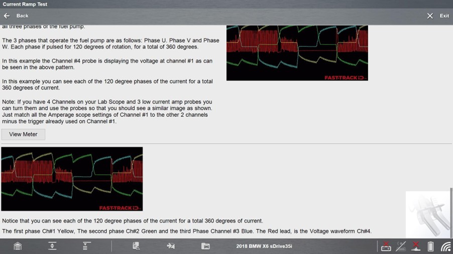
BMW X6 sDrive35i 2018, 3 Phase Fuel Pump Test Overview
The BMW Guided Component Test:
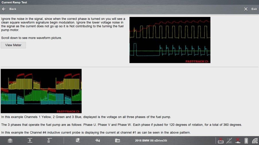
• Monitors all three motor phases simultaneously
• Displays positive and negative current flow
• Uses multi channel, full color waveform displays
• Clearly illustrates motor phase timing and balance
A clean, even pattern across all phases confirms a healthy pump and control circuit. Distorted or unbalanced patterns point to wiring, module, or pump issues.
Diagnostic Best Practices
A repeatable diagnostic workflow improves accuracy and reduces comebacks:
1. Verify the customer complaint
2. Perform a complete pre scan
3. Use Guided Component Tests to verify suspected components
4. Complete repairs as required
5. Perform any required resets or relearns
6. Road test the vehicle
7. Perform a post scan to confirm the repair
Testing components before replacing them, then again after repair, is the most effective way to prevent comebacks.
Why This Functionality Is Essential
Snap on provides the guided workflows and testing capabilities technicians need to verify component operation accurately and efficiently.
Key capabilities include:
• FTID guided diagnostic workflows
• Automatic scope configuration
• Guided Component Tests with known good waveform references
• Enhanced, detailed component images
This functionality eliminates guesswork by combining scanner direction with scope-based verification, helping technicians test and verify rather than guess, replace unnecessary parts wasting both time and money.
Why Guided Component Testing Delivers Accurate Vehicle Diagnostics
Modern electrical and electronic systems cannot be diagnosed reliably with scan data alone. Processed data shows what the control module thinks is happening, but it does not always reveal the true cause of a failure.
Fast-Track® Guided Component Tests give technicians the ability to see what components are doing in real time, identify opens, shorts, and resistance related faults, and verify repairs using known good waveform references.
Test don’t guess is more than a tagline. It is a diagnostic philosophy that leads to fewer comebacks, better repairs, and greater diagnostic confidence.
FAQ’s
1. Why isn’t scan data alone enough to diagnose modern electrical faults?
Scan data reflects what the control module reports after the signal has been processed through software logic and fault thresholds. Intermittent dropouts or distortion may not exceed those thresholds, allowing a fault to exist without setting a code. Scope testing allows technicians to view the signal directly at the component and identify issues that scan data may miss.
2. What does “front door vs back door” data mean in diagnostics?
The front door represents raw signal data entering the control module directly from a component. The back door represents processed data leaving the module after logic and thresholds are applied. Scan tools view back door data, while scope testing allows technicians to see front door data, which is essential for identifying the true cause of a failure.
3. What types of component failures are Guided Component Tests best at identifying?
Guided Component Tests are especially effective for diagnosing open circuits, short circuits, and resistance‑related faults. These failures often pass basic voltage or continuity checks, but become visible when the component is tested under operating conditions using waveform analysis.
4. Why are known‑good waveform comparisons important?
Knowing what a correct signal should look like removes guesswork. Known‑good waveform references give technicians an immediate visual benchmark, making it easier to determine whether a component is operating normally or failing electrically.
5. How do Fast‑Track Guided Component Tests reduce comebacks?
By providing guided setup, automatic scope configuration, and known‑good waveform comparisons, Fast‑Track Guided Component Tests help technicians verify faults before replacing parts and confirm repairs afterward. This test‑before‑replace and test‑after‑repair approach significantly reduces repeat repairs and misdiagnosis.