Many vehicle manufacturers are now using Magneto-Resistive Hall Effect Sensors (often referred to as Active Type Sensors) for detecting speed, direction of rotation and ‘standstill’ of a rotating assembly. The accuracy of the technology allows many parameters to be detected, which provides the necessary data for an increase in functionality, such as using the automatic parking brake or automatic hill descent technology.
Modern brakes rely on this technology for precise control of the vehicle’s braking system so it goes without saying, a basic understanding is critical to ensure you are confident that repairs are completed correctly and that the vehicle is safe to drive once the job is done. The sensor construction and measuring related waveforms is a useful place to start when getting to grips with complex brake system faults. Take a look at the article below to learn more.
Sensor Construction
The image below shows how Active Wheel Speed Sensors can detect the direction of rotation. There are two Magneto-Resistive Element (MRE) Sensors close to the phonic wheel, this is the method used to detect the direction of rotation. The sensor integrated circuit can monitor the output phase from both sensors to determine the direction of rotation. A change in magnetic resistance is detected when the phonic wheel rotates. The output from the MRE sensors is interpreted by the evaluation electronics in the sensor’s integrated circuit and an output voltage can be measured at the sensor. The system’s control module uses this output voltage to calculate rotation speed and direction of rotation.
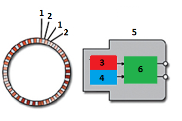
- North Pole
- South Pole
- MRE sensing element 1
- MRE sensing element 2
- Sensor assembly
- Signal Processing
The diagram below displays the difference in output voltage pulse width depending on direction of rotation, note the frequency remains the same, the pulse width is the only variable.
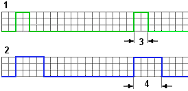
- Forward direction
- Reverse direction
- Processed output voltage (Forward)
- Processed output voltage (Reverse)
Standstill Monitoring
Another feature of active speed sensors is the ability to monitor ‘standstill’, this is when the rotating assembly is stopped.
The diagram below displays the output signal for such a condition:
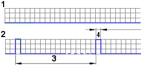
- Internal sensor output
- Actual sensor output
- Delta between pulses – 700 ms
- Processed output voltage
Sensor Output Voltage
The sensor output voltage signal can be superimposed on the ground wire or the supply wire to the sensor. Both types can be tested with an oscilloscope, and both are shown below:
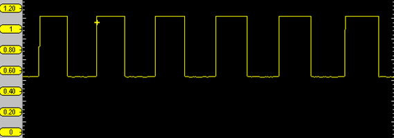
Signal superimposed on supply wire, oscilloscope coupled to AC to display detail.
Signal superimposed on ground wire.
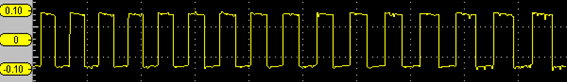
Measured Current Flow
The output current from an active speed sensor is approximately 7mA to 14mA. A micro-amp clamp was used to observe the output current from an active wheel speed sensor.

The red trace displays the output voltage: 0.5 Volts to 1.1 Volts. The yellow trace displays current flow: 9 mA to 17 mA. N.B. use the conversion of 10 mV is equal to 1 mA.
Check out Guided Component Tests on compatible Snap-on platforms for vehicle-specific waveforms and pin assignments.