How to setup
Snap-on's pressure transducer adaptor (EEMS324PSA) is compatible with Snap-on's Handheld diagnostic tools that include a scope; MODIS, TRITON, VERUS, and ZEUS. There are 3 different types of Snap-on pressure transducers that come in either 0 – 100 PSI, 0 – 500 PSI, or 0 – 5000 PSI, and which transducer you use will depend on what we want to measure. You will need to connect the transducer to the scope by using either a split lead adapter for a 4-channel scope, or a PSA adapter that will work with 2 or 4- channel scopes and is battery powered.
Case Study
This case was with a 2002 Ford Explorer, a no-start after a PCM install. The PCM was replaced at another garage, so the full history was not available.
The engine did start after a parameter reset, but a short time later it wouldn't start again. So, some initial checks were carried out;
-
The PCM was checked to ensure the right one was fitted and working correctly – that was ok
-
A fuel check was conducted, using a manual analogue gauge
When checking the fuel, it was noticed that when the engine was cranked, the needle on the manual gauge was fluctuating wildly, almost following the pulse of the engine. Now you may expect to see a little fluctuation, but not to that extent, so that prompted a closer look using Snap-on ZEUS and pressure transducer.
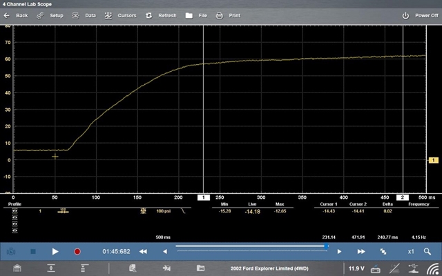
The pressure transducer was connected into the fuel line. As the key was turned in the ignition it could be seen that the fuel pressure builds slowly (as it should), up to a little over 60 PSI, which is normal pressure for this particular vehicle.
But then when cranking begins, a pattern starts to occur. The pattern goes from a little over 60psi down to 20 psi and then up to a little over 40psi and then down to 20psi and 40 and 20 and back and forth. You can see that this corresponds to where the fluctuation was seen on the manual fuel gauge. This equates to a huge drop in pressure when the vehicle is turned over (cranked).
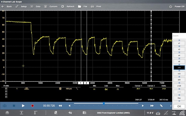
So, if fuel pressure is being lost, perhaps that's why it's not starting.
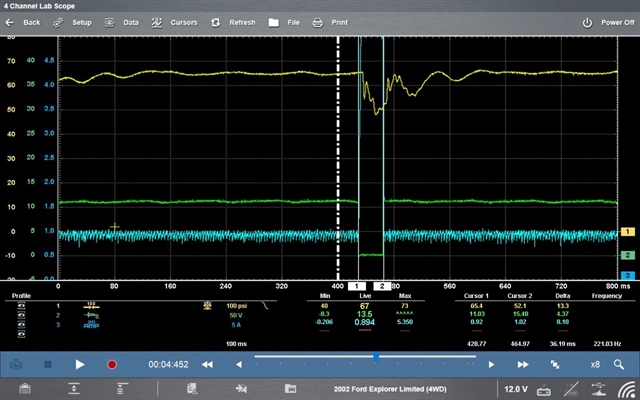
It’s time to investigate a little further by hooking up to an injector and checking both the injector and the fuel pressure at the same. In this example, we have the pressure on the yellow channel (channel one), the green channel is the fuel injector (power voltage), and then the blue channel is the AMP probe, to make sure that fuel injector is opening.
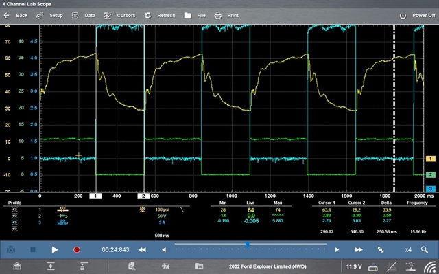
By looking at all these parameters together, we can see that when the fuel injector opens, that is exactly when the fuel pressure drops. It is a big drop - from 60psi to 30psi in this case. This huge drop every time it cranks means the vehicle is not able to build up enough pressure. It’s basically bleeding off too much when it fires. Now, why is it bleeding off so much pressure?
If we look at the ‘On Time’ for that injector, it's 250 milliseconds (0.25 secs). That is a large amount of ‘on time’, during normal temperatures. It is significantly more than it should be and so needs to be investigated.
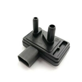
There were also many codes in the vehicle. On review of the codes, it was found that the DPFE sensor was shorted on the VREF circuit. The DPFE is the EGR differential pressure sensor and it had shorted when it was plugged in. The 5-volt reference circuit had dropped to about 0.5 volts, (4/10ths of a volt). If it was unplugged, it went back up to five volts. That determined that the sensor was shorted internally, pulling that voltage down to ground.
The sensor was replaced and the same test was repeated to verify that same pattern was no longer happening. The same process was followed to hook up the channels and we can see that the pressure stays around 60psi and then it drops down to 50psi and then builds its way back up. We can see where the injector closes and the pressure builds until we see the next injector firing event happens. And, the ‘on time’ is back down to approximately 36 milliseconds – a much more reasonable ‘on time’.
Those readings are now back in line with what is expected when operating correctly.
So, what happened? The hypothesis is if it shorted down to 0.5 volts, (via the 5-volt reference system (VREF), those other sensors that are connected to that 5-volt reference system are then affected. When the voltage on that one sensor is pulled down, then all of those connected sensors are going to read incorrectly. So, in this case, it appears that the cooling temp sensor failed on the low side, and that is what lead to that injector ‘on time’ being affected.
This is just one way of hooking up a scope and using a pressure transducer to help you visualize the pattern and aid your diagnosis.
More information and examples can be found within the Guided Component Test area of the Snap-on MODIS, TRITON, VERUS and ZEUS. There you will find a 15-minute Pressure Transducer Diagnostic class and a 10-minute Running Compressions Waveform class.
As well as finding helpful classes on your Snap-on handheld tools, you can also benefit from our extensive library of educational YouTube videos. This particular case study was just one of the examples that was covered in Episode 32 – so watch the recording and listen to some more examples.
Watch Epsiode 32 - Pressure Transducer Diagnostics