The Clear View Flag Tracker is a feature that can help a technician to identify when a data parameter (PID) value goes out of specification. Let's take a look at how a technician can use this exclusive Snap-on feature to quickly diagnose a faulty EGR position sensor.
A minimum and maximum value can be set for a particular Data Parameter (PID) and if either the upper or lower limit is exceeded a solid red line will appear on the data graph on the PID. The other data parameters will have a dotted line at the point where the limits were breached.
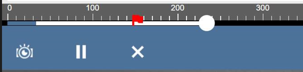
Also a red flag is dropped on the X-axis at the time the PID is breached. This makes it easy for a technician to quickly identify when the issue occurred and return to that point in the data buffer. Clicking the flag will bring the graph back to that point in the buffer.
Below is an example that shows how a technician would use this feature to diagnose a faulty EGR Position Sensor circuit.
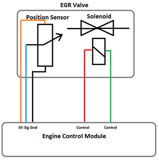
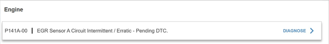
A vehicle has an EGR Position Sensor circuit fault code. The position sensor has a 5 volt supply, ground and a signal which ranges from 0.9 volts (EGR Valve fully closed) and 3.9 volts (EGR Valve fully open).
An intermittent fault relating to the EGR position sensor can be difficult to troubleshoot.
Monitoring the live data is critical for identifying the cause of such a fault. Most vehicles support PIDs for the EGR Solenoid (Command) and EGR position (feedback).
Data Parameters:
- EGR Valve Position Sensor (V)
- EGR Valve Position (%)
- EGR – Commanded (%)
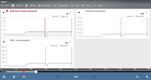
As the fault related to the EGR Position sensor, an alarm was armed for the EGR Valve Position Sensor data parameter. The minimum value was set at 0.3 volts and the maximum value set at 4.2 volts. Note, with the EGR valve closed the voltage is ≈0.9 volts.
On a road test the fault occurred, the voltage dropped below 0.3 volts. You can see the solid red line on the graph when the voltage dropped from 1.6 volts to 0.1 volts. The dotted red lines indicate when the flag was set on the remaining PIDs. We can also see where the flag was set on the X-axis. This is especially useful if the technician is unable to review the data and the buffer continues to fill. It is easy to return to the point where the PID value was breached.
With the vehicle back in the workshop a wiggle test was carried out on the electrical connector. The sensor voltage dropped regularly during this test. This drop in voltage could be due to a short to ground or open circuit in the sensor circuit, so the wiring and electrical connector were tested and no faults found. Further investigation revealed the position sensor signal pin on the EGR valve was faulty. This meant the EGR valve would have to be replaced.
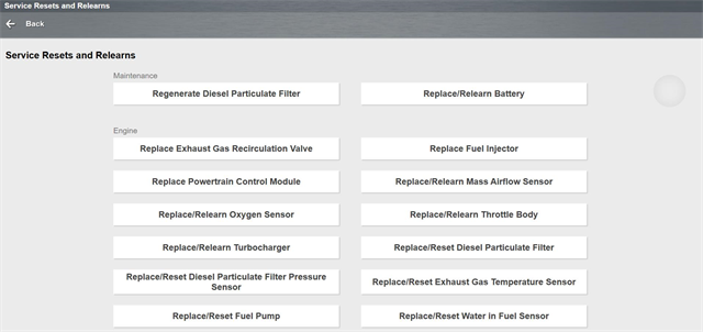
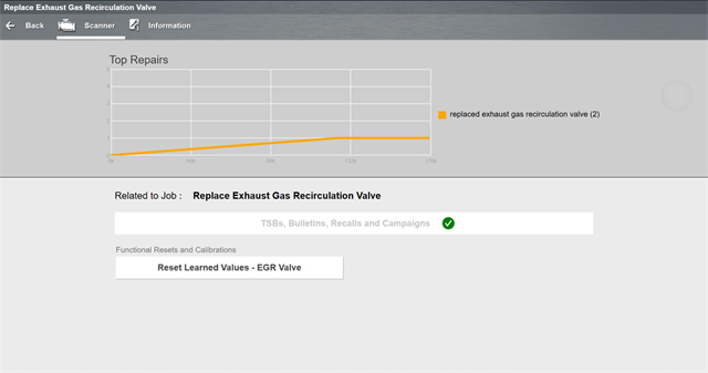
With the EGR valve replaced the EGR learned values may need to be reset. Using the Service Resets and Relearns Menu the technician can quickly and easily carry out the special function.

The fault codes were cleared and the vehicle road tested. The vehicle preformed as expected.