Step 1 - Find the centre line of the front axle
The first step is the find the centre point of the front axle in the vertical axis. This is made more simple by using a laser. Mark the floor at the centre point of the wheel.

Step 2 - Use a plumb-line to find end of vehicle, use either a step or tow-hitch depending on fitment
Next, we must find the end point of the vehicle. This vehicle is fitted with a tow-hitch, so a plumb line was attached to the ball of the hitch and allowed hang. The point the plumb line touches the floor was marked.

Now the targets can be placed on the floor behind the vehicle. There are three targets which are numbered and have directional arrows to ensure correct placement.
Step 3 - Place the targets on ground behind vehicle

The centre line of the target must be located 40cm or 400mm from the end point of the vehicle. Again, a laser is used to ensure the target is in-line with the rear if the vehicle. The laser should intersect the centre line of all three targets.
Step 4 - Measure a distance of 400mm/40cm from the end of the vehicle to the centre of the middle target


Next, the laser must be used to find the centre point of the vehicle. The beam must intersect the centre point of the manufacturer badge and the rear camera lens.
Step 5 - Align Targets with centre line of vehicle


This image shows the centre of the camera
Once again, ensure the centre of each target is correctly aligned. This line will be used for the final measurement so the laser can be left in this position.
Step 6 - Centralise the targets


A measuring tape must now be used to measure the distance from the centre point of the front axle (step 1) to the centre point of the targets (step 6).


Step 7 - Measure the distance from the centre of the front axle to the centre of the targets
Record the measurement as this must be input into the Diagnostic Scantool during the alignment procedure.


View of the vehicle from the rear.

This is an overhead view of the target placement.
Now that we have the target correctly aligned and the measurement from the front axle to the target measured we can connect the scantool to the vehicle and carry out the diagnostic procedure.
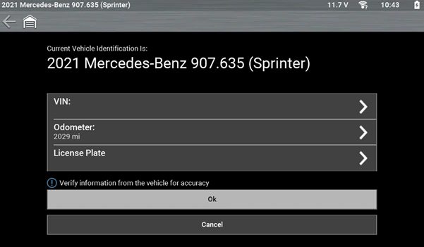

Connect the scantool to the data link connector and select 'Backup Camera'.

Select calibration of reversing camera.


Enter the measure value (6580mm/658cm)


Following the calibration, check for DTC and check operation of the backup camera.