Modern vehicle diagnostics continues to become more complex, with systems interacting across multiple control units and faults not always presenting in a straightforward way. Technicians are often required to interpret fault codes, analyse live data, and follow structured test procedures, but even then, the root cause is not always clear.
Troubleshooter Tips That Deliver Real Fixes
Rely on us to provide all the Troubleshooter tips you need to be the best
In many cases, valuable time is spent searching through OEM procedures, online forums, or relying on past experience to piece together a diagnosis.
Troubleshooter Tips simplify this process by combining OEM information with real-world repair knowledge, allowing technicians to identify common faults quickly and with greater confidence. Instead of relying solely on theory, technicians can apply proven fixes based on what has already been seen and resolved in workshops.
From Component Testing to Real-world Diagnosis
Traditional diagnostics focuses on testing components and following fault codes, but real-world faults do not always align with expected outcomes.
Troubleshooter Tips enhance this process by helping technicians:
This shifts the diagnostic approach from simply asking:
“What should this fault be?” to “What has actually fixed this before?”
Where Time Is Lost in the Workshop
A significant amount of diagnostic time is lost to:
Troubleshooter Tips reduce this by narrowing the focus and highlighting the most likely causes first. By bringing together code information, symptoms, and real-world fixes, technicians can move from diagnosis to repair more quickly.
What’s New: Troubleshooter Tips Coverage
New Troubleshooter Tips with supporting images have been added across key systems, helping technicians diagnose common faults more effectively and avoid repeat repairs.
SEAT® Leon 1.6L Diesel (2010–2013)

Heater Matrix Fault, Silica Contamination
DTC: B10BE-13 Fresh Air Blower, Front – Open Circuit
A common issue on this vehicle is poor heater performance caused by contamination within the cooling system. The root cause is often the breakdown of the silicate bag within the expansion tank, allowing debris to circulate through the system.
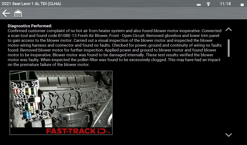
Diagnostics performed: Customer complaint confirmed: no hot air from the heater system, and the blower motor was also inoperative. A pre‑scan revealed DTC B10BE‑13 (Fresh Air Blower, Front – Open Circuit).
The glovebox and lower trim were removed to access the blower motor. Visual inspection of the motor and wiring showed no obvious faults. Power, ground, and continuity were checked and found to be correct. The blower motor was removed for further testing. With direct power and ground applied, the motor remained inoperative, confirming failure.
The blower motor was replaced, and the rheostat transferred from the original unit. A new pollen filter was also installed. After clearing codes, the system was brought up to operating temperature and tested, heating performance initially returned to normal.
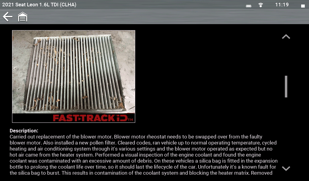
However, a visual inspection of the coolant revealed significant contamination. On these vehicles, a silicate bag within the expansion tank is designed to prolong coolant life, but it is a known issue for the bag to burst, allowing debris to circulate and block the heater matrix. Further inspection confirmed the heater matrix was restricted and required replacement.
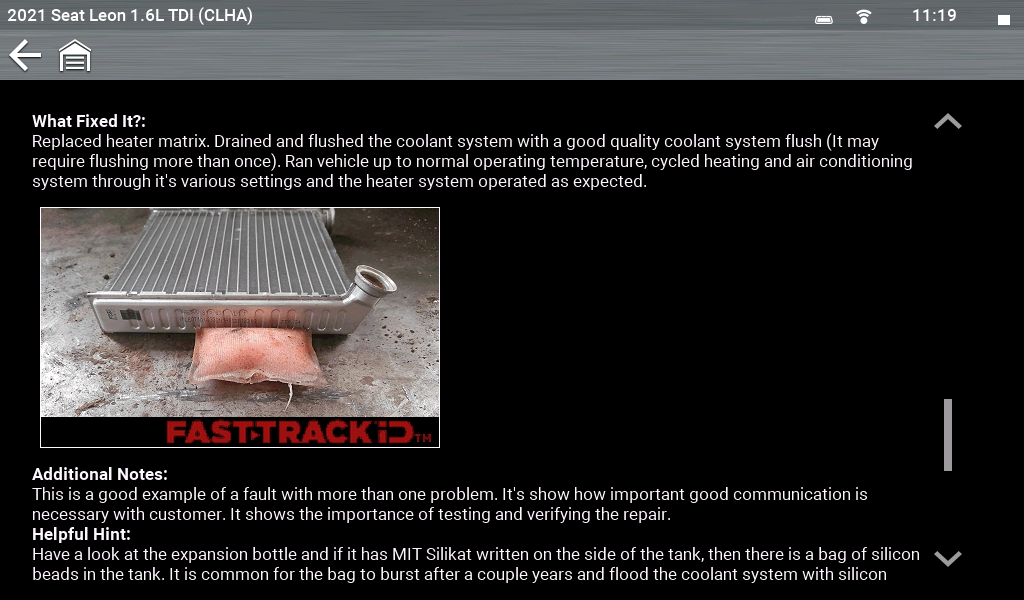
Troubleshooter Tips provide clear insight into this failure pattern, helping technicians identify the root cause rather than replacing components based on assumption. By applying simple diagnostic checks, such as comparing inlet and outlet temperatures, restriction can be confirmed quickly without unnecessary disassembly.
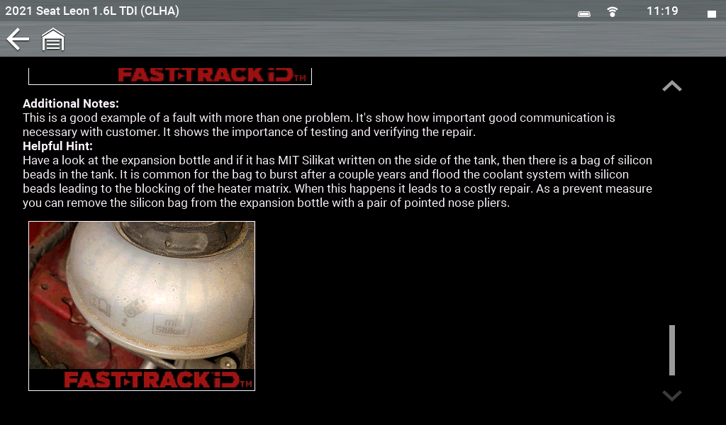
A common mistake is to replace the heater matrix without addressing the underlying contamination. If the system is not thoroughly flushed, debris can remain and the fault can return.
To prevent repeat issues:
Troubleshooter Tips provide clear visual guidance for this issue, helping technicians quickly identify the root cause and avoid unnecessary repeat repairs.
Toyota® Avensis 2.0L Diesel (2008–2018)

No Start Condition – High‑Pressure Fuel Pump
DTC: C1201 Engine/EV Control System Fault
Customer complaint confirmed – vehicle would not start. The vehicle had been recovered to the workshop following recent repair work, including replacement of the fuel filter and high‑pressure fuel pump.
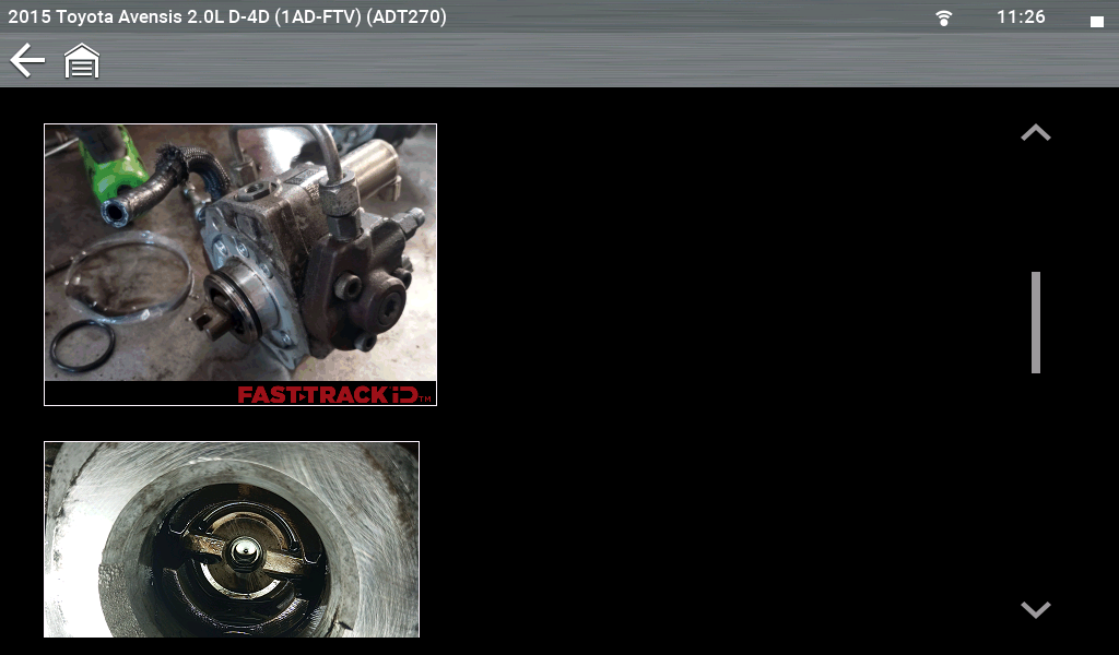
A scan tool check revealed DTC C1201 (Engine/EV Control System Fault), a generic code commonly associated with extended cranking and a no‑start condition. Initial checks focused on the low‑pressure fuel system. The system was primed using the hand primer on the fuel filter and was found to operate correctly, with no leaks detected. The engine was cranked while monitoring live data, where it was noted that the fuel pressure parameter was not present, indicating no pressure build‑up.
Attention then turned to the high‑pressure fuel system. The suction control valve wiring and connectors were inspected and found to be secure, with no visible damage. Electrical checks using a multi-meter confirmed no short or open circuits, verifying correct operation of the suction control valve. With no fuel pressure being generated and electrical checks confirming system integrity, the high‑pressure fuel pump became suspect. The pump was removed for inspection, where it was discovered that the coupler between the camshaft drive and fuel pump was missing.
This confirmed that, during previous repair work, the coupling had been lost, resulting in no mechanical drive to the fuel pump.
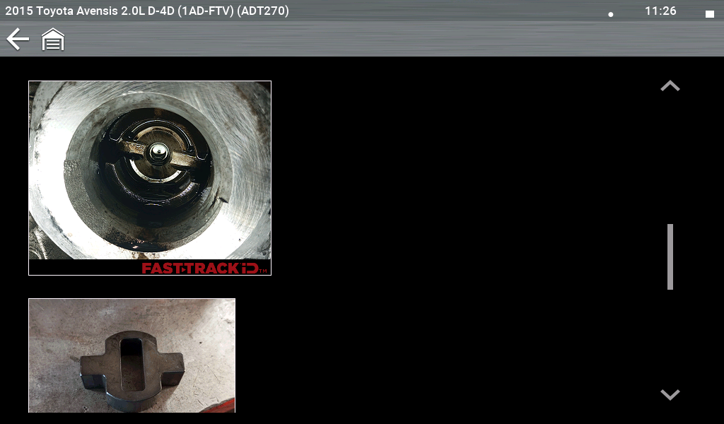
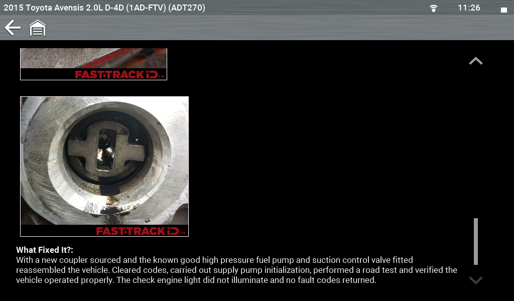
What fixed it? A replacement coupler was sourced and installed. The high‑pressure fuel pump and suction control valve were refitted, and the system reassembled.
Fault codes were cleared, and a supply pump initialisation was performed. Following this, the engine started normally. A road test was carried out and confirmed correct operation, with no warning lights present and no faults stored during post‑repair scanning.
A common cause of the fault is the missing coupling, resulting in the pump not being driven.
To avoid this:
Troubleshooter Tips highlight this as a known issue, allowing technicians to identify the root cause quickly and avoid extended diagnostic time.
Mercedes Benz® SLK 200 1.8L Petrol (2004–2011)

Mass Air Flow (MAF) Sensor Fault
DTC: P200A Bank 2/5 Hot Film Mass Airflow Sensor Check Engine Light on
Mass air flow sensors are critical for measuring incoming air and allowing the engine control unit to calculate the correct fuel delivery.
Typical faults present with:
Technicians often assume that a fault code pointing to the MAF sensor confirms the component has failed. This can lead to premature replacement without proper testing.
Correct diagnosis requires:
Many faults are caused by external factors such as wiring issues or intake contamination rather than sensor failure.
Best practice includes:
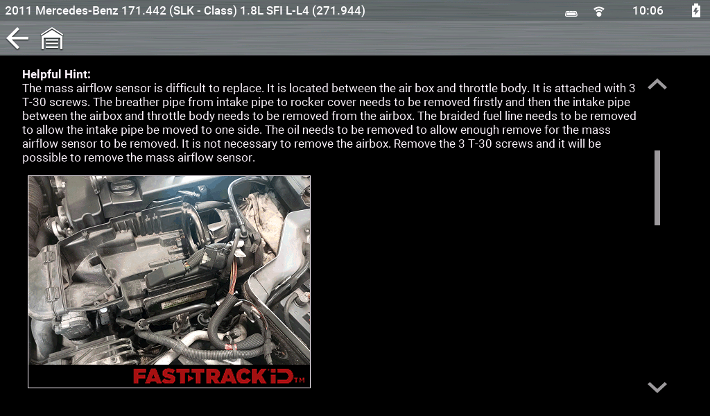
Troubleshooter Tips provide visual examples and known fault patterns to help technicians confirm the issue before replacing components.
Diagnostics performed:
Customer complaint confirmed – check engine light illuminated. A scan tool pre‑scan displayed DTC P200A (Bank 2/5 Hot Film Mass Airflow Sensor). Initial inspection of the mass air flow (MAF) sensor wiring harness and connectors found no loose connections or visible damage. With the ignition on and engine off, voltage and ground supply at the MAF sensor were verified using a multi-meter and found to be correct.
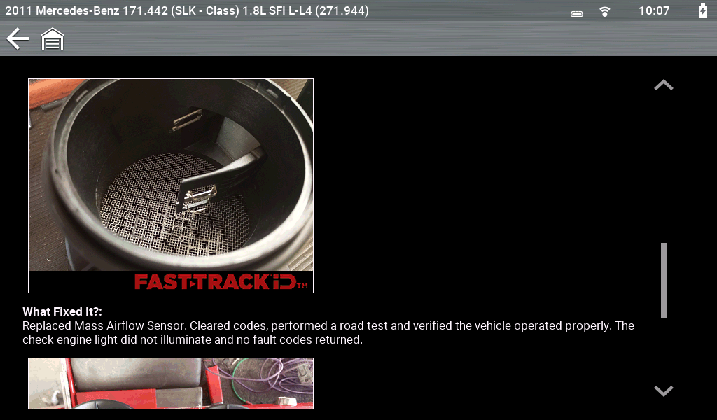
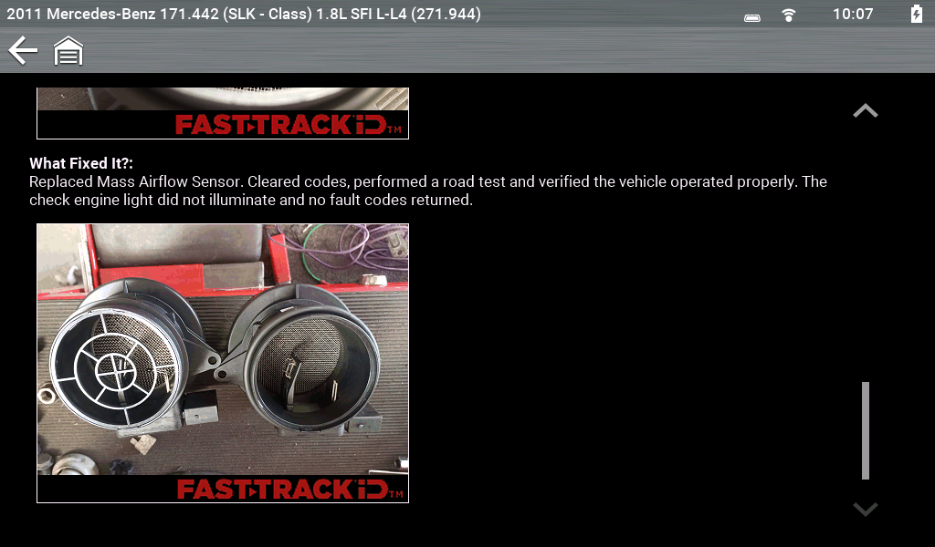
Attention then turned to the intake system. The airbox cover was removed and the air filter inspected, where it was found to be contaminated. Further inspection of the MAF sensor revealed damage to the sensor’s heating element, confirming the sensor was faulty.
What fixed it?
The mass air flow sensor was replaced and codes were cleared. A road test confirmed correct vehicle operation, with no recurrence of the fault. A post‑scan verified no DTCs were present and the check engine light remained off.
A Smarter Approach to Diagnosis
Across all three examples, the same key lessons apply:
Troubleshooter Tips provide the missing context by showing how faults appear in real-world scenarios, helping technicians make more informed decisions earlier in the diagnostic process.
Why This Matters
Troubleshooter Tips are not just an additional feature; they fundamentally improve the way diagnostics are performed.
By using experience based insight, technicians can:
In many cases, a single piece of information can save hours of unnecessary testing.
Working Smarter with Snap‑on® Fast-Track® Troubleshooting Workflow
Troubleshooter Tips are fully integrated into Snap-on diagnostic platforms through Fast‑Track Troubleshooting Workflow, allowing technicians to access relevant information directly within their workflow.
This provides:
With everything available in one place, technicians can focus on resolving faults efficiently without interrupting the diagnostic process.
Modern diagnostics is no longer just about testing components — it is about understanding how systems behave in real-world conditions.
By combining OEM data with proven repair knowledge, Troubleshooter Tips enable technicians to diagnose more accurately, work more efficiently, and complete repairs correctly the first time.
FAQ’s
1. When should I use Troubleshooter Tips during the diagnostic process?
Troubleshooter Tips should be used early in the diagnostic process, ideally after reviewing fault codes and live data. Accessing them at this stage helps identify known issues and common fixes before following unnecessary or time‑consuming test procedures.
2. How do Troubleshooter Tips improve diagnostic accuracy?
Troubleshooter Tips combine OEM data with real‑world repair insights, allowing technicians to see what has fixed the same issue in other vehicles. This helps confirm the likely root cause more quickly and reduces the risk of misdiagnosis.
3. Can Troubleshooter Tips help with faults that don’t have a fault code?
Yes. Troubleshooter Tips include both code‑based and symptom‑based guidance. This means they can provide valuable diagnostic direction even when no DTC is present, helping technicians identify faults based on real‑world symptoms.
4. How do Troubleshooter Tips help reduce repeat repairs and comebacks?
By highlighting known fault patterns and correct repair procedures, Troubleshooter Tips ensure that the root cause is addressed the first time. This helps prevent incomplete repairs, unnecessary part replacement, and repeat workshop visits.
5. What is the difference between Troubleshooter Tips and Guided Component Tests?
Troubleshooter Tips help identify likely faults based on real‑world experience, while Guided Component Tests are used to verify component operation and confirm the diagnosis. Together, they provide a structured approach to both identifying and validating the repair.
*This article is intended for informational purposes only and is designed to provide general technical insight. It is not intended to serve as step‑by‑step repair or diagnostic instruction. Always follow manufacturer‑approved procedures and safety guidelines when carrying out vehicle diagnostics or repairs.