Modern engines rely heavily on forced induction systems to meet the performance, efficiency, and emissions targets required by current vehicle design standards. With increasing pressure on manufacturers to reduce engine displacement while meeting stricter emissions legislation, forced induction has become a fundamental part of engine development.
By enabling smaller-capacity engines to produce higher power output, while also supporting leaner combustion and improved efficiency, turbocharging and supercharging allow manufacturers to meet these demands without compromising capability. As a result, forced induction systems are now common across both petrol and diesel applications.
However, when boost-related faults arise, they can often lead technicians down the wrong diagnostic path, resulting in unnecessary component replacement and repeat repairs.
With Guided Component Tests (CTM) and integrated Troubleshooter insights, technicians now have the ability to quickly validate components and identify root causes with confidence. Check out our related videos about component testing here.
Why Forced Induction?
Forced induction systems are used to improve engine efficiency and performance while meeting increasingly strict emissions targets.
By compressing the intake air, these systems enable:
- Increased power output from smaller engines
- Improved fuel economy through leaner air-fuel mixtures
- Reduced emissions through more efficient combustion
This allows manufacturers to achieve a balance between performance and regulatory compliance.
Key Forced Induction Components
A typical forced induction system may include:
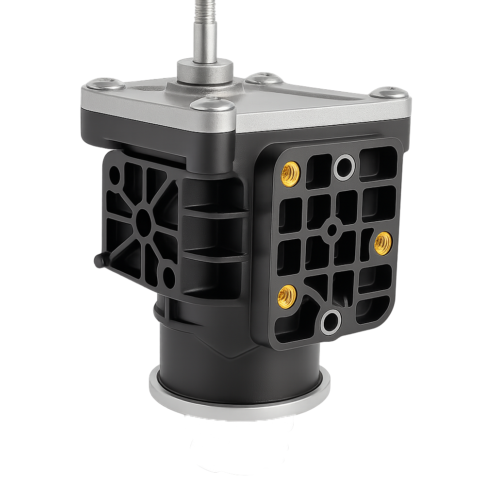
- Supercharger
- Turbocharger
- Variable Geometry Turbocharger (VGT)
- Wastegate
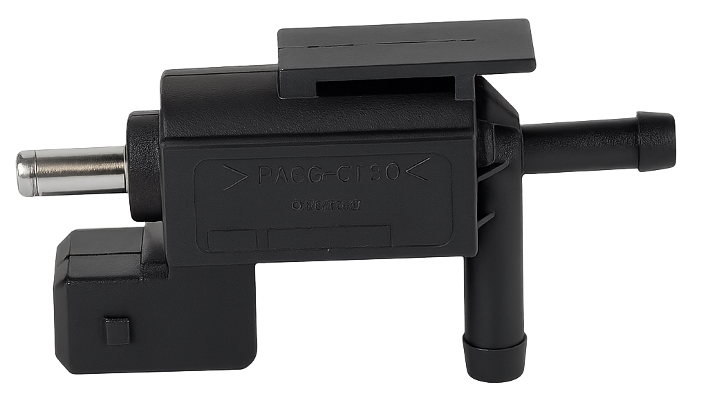
- Boost controller (wastegate control solenoid)
- Blow-off / recirculation valve
- Intercooler
Understanding the role of each component is essential when diagnosing boost-related faults.
Superchargers
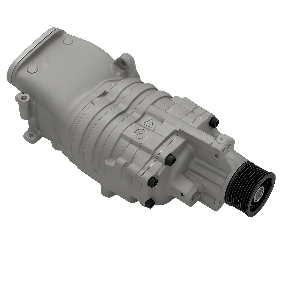
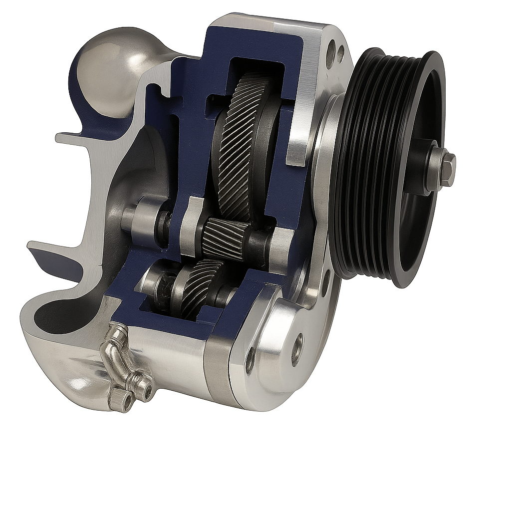
A supercharger is a belt-driven air compressor, powered directly by the engine.
Operating Characteristics:
Common Types:
Roots-type: Positive displacement, consistent boost delivery
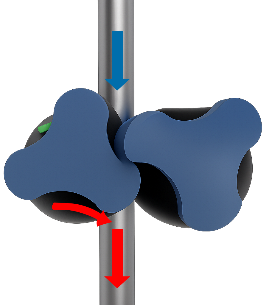
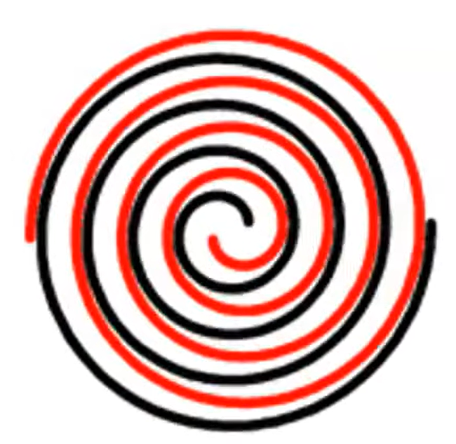
Scroll-type: Smooth airflow characteristics
Centrifugal: Shares characteristics with a turbocharger, often described as a hybrid between a turbo and a supercharger
While superchargers provide instant response, they do so by consuming engine power.
Case Study: 2006 Mini Cooper S
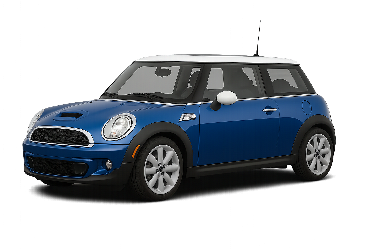
A 2006 Mini Cooper S presented with:
A pre-scan reveals:
Initial Diagnostic Path
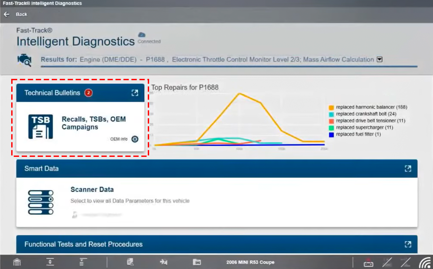
Technical Service Bulletins relating to this DTC identify possible causes:
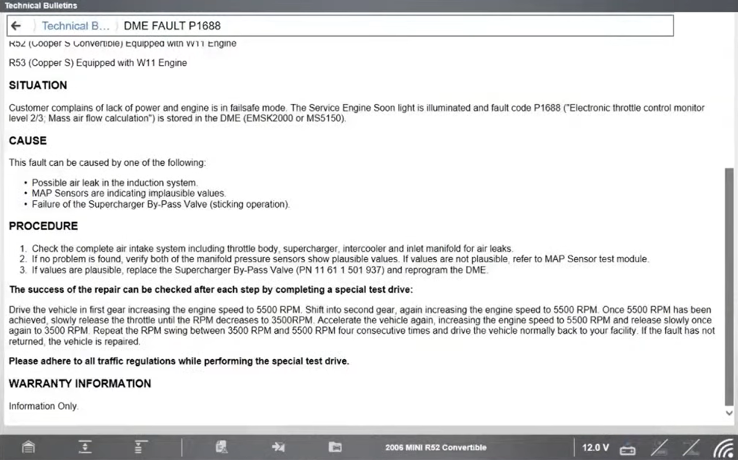
When performing a DIS/GT1 test module, the guided diagnostic path can indirectly lead towards replacement of the DME control module, rather than identifying the true root cause.
A correct diagnostic step at this stage is to:
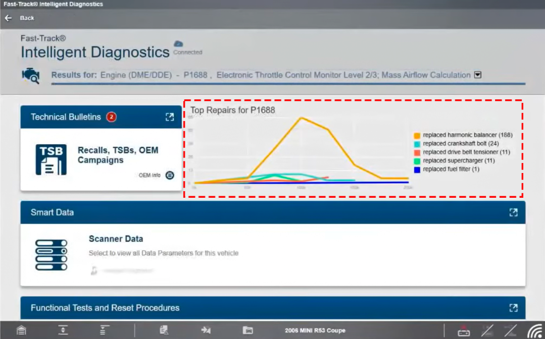
Fast-Track Top Repairs Insight
Analysis of Fast-Track Top Repairs data for this fault highlights that the most common repair is:
This points towards a mechanical issue rather than an electronic fault.
SureTrack® Expert Information – Real Fixes from Techs with similar issues
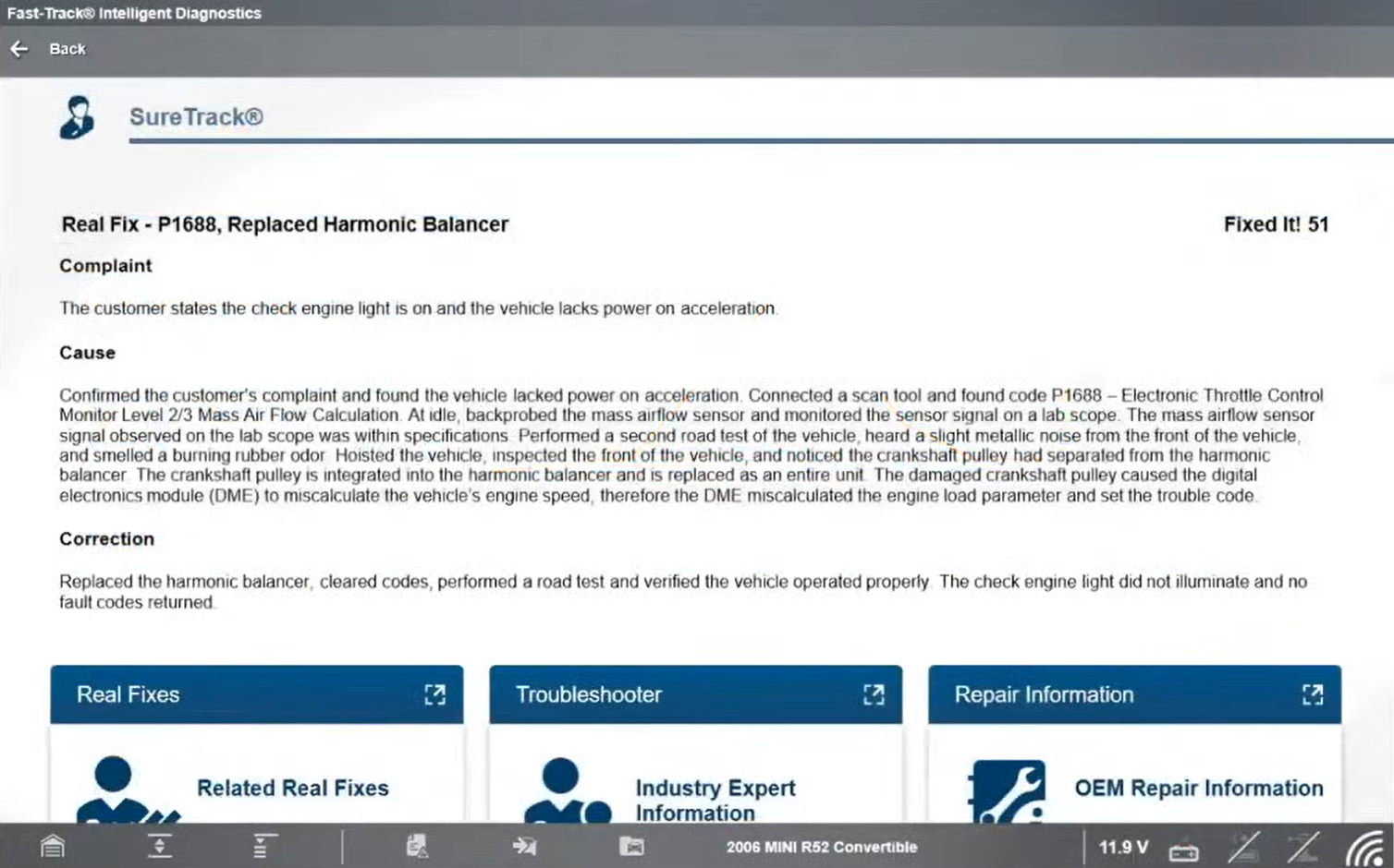
Further investigation using SureTrack Expert information identifies a verified real-world repair:
During testing there was a metallic noise detected from the front of the engine and a burning rubber smell. Further inspection revealed that the crankshaft pulley had separated from the harmonic balancer, the pulley is integrated into the balancer and replaced as a single unit.
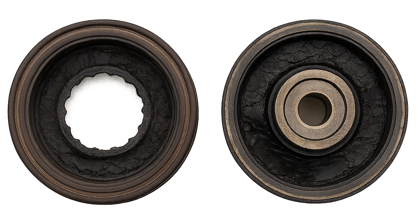
Mini P1688 damaged crankshaft pulley
This failure caused:
Repair and Verification
Result:
Key Insight:
Fault codes and guided test paths can indicate likely causes—but not always the root cause.
Always validate mechanical components alongside electronic diagnosis.
Turbochargers: System Overview and Operating Principles
Turbochargers
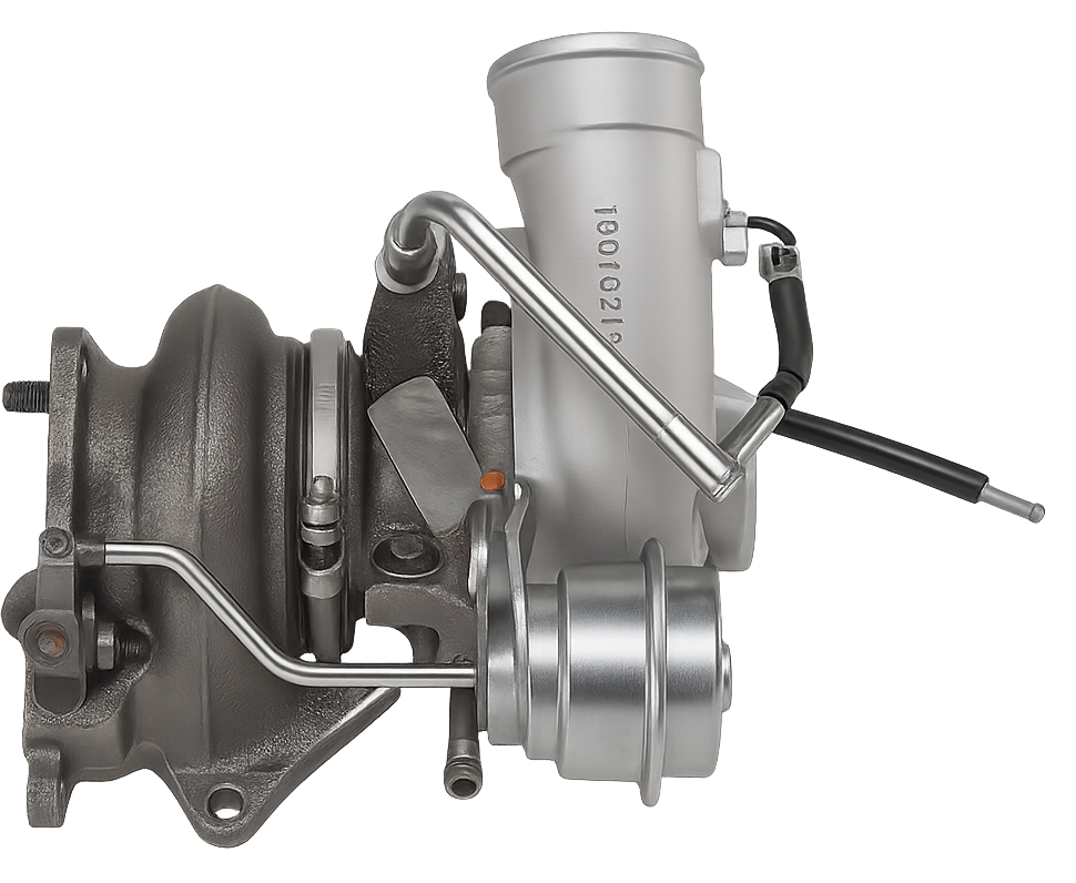
A turbocharger is an exhaust-driven air compressor, using exhaust gas energy to increase intake air pressure.
Operating Characteristics:
Common Types:
Common Turbocharger Issues
Turbocharger failures are typically mechanical in nature.
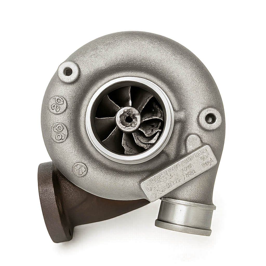
Common causes include:
At extremely high operating speeds, inadequate lubrication can result in:
Boost Control System
Wastegate
Boost Controller (Wastegate Control Solenoid)
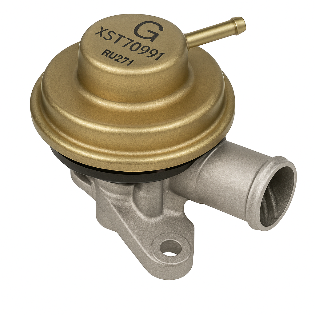
Blow-off / Recirculation Valve
This prevents compressor surge and protects the turbocharger.
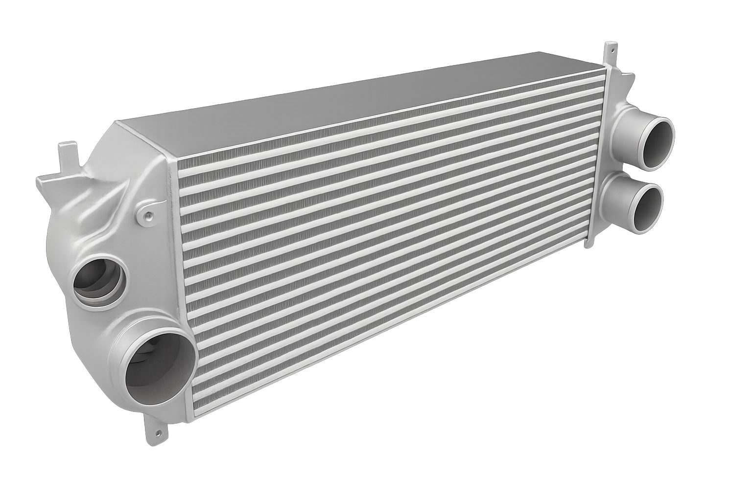
Intercooler
Compressing air increases temperature and reduces density.
The intercooler:
Types include Air-to-air and Air-to-water each designed to manage charge air temperature under different operating conditions.
Diagnostic Challenges
A common scenario is a vehicle presenting with a boost-related DTC.
Typical outcomes include:
In many cases, the issue lies in the diagnostic approach, not the component itself.
Why Faults Occur
Boost-related faults may be caused by:
Key Principle
A fault code identifies a symptom, not the failed component.
Diagnostic Approach: Structured and Efficient
Recommended Diagnostic Sequence
-
Read fault codes
-
Assess live data
-
Check known issues and guidance
-
Perform Guided Component Tests (CTM)
-
Inspect mechanical components
This ensures accurate root cause identification early in the process.
Common Pitfalls in Boost Diagnosis
Key Takeaway
Component testing often takes minutes, and less time than replacing unnecessary parts. Ultimately time is money also prevents wasting money on unnecessary parts. Check out more related videos about component testing here.
Achieving First-Time Fixes on Forced Induction Systems
Forced induction systems are essential in modern engines, but effective diagnosis requires more than reading fault codes.
Combining:
-
Guided Component Testing enables faster, more accurate repairs and greater certainty when handing the vehicle back to the customer, reducing the chances of a comeback (or worse, a don’t come back).
FAQ’s
Q1: What is forced induction and why is it used?
Forced induction systems, such as turbochargers and superchargers, compress intake air to increase engine power output, improve efficiency and reduce emissions, allowing smaller engines to deliver higher performance.
Q2: Do boost-related fault codes always indicate a faulty component?
No. Boost-related DTCs often indicate a symptom rather than the root cause. Issues such as air leaks, restrictions, or mechanical faults can affect sensor readings and trigger fault codes.
Q3: What are common causes of turbocharger or boost system faults?
Common causes include air leaks, blocked or restricted pipework, oil supply issues, mechanical wear, and contamination—rather than the turbocharger or sensor itself.
Q4: How do Guided Component Tests improve diagnosis?
Guided Component Tests provide structured, step‑by‑step procedures, known‑good reference data and real‑world insights, allowing technicians to validate components quickly and accurately identify the root cause of faults.
Q5: What is the best approach to diagnosing forced induction faults?
A structured approach is key: read fault codes, assess live data, check known issues, perform Guided Component Tests, and inspect mechanical components. This ensures accurate diagnosis and avoids unnecessary parts replacement.
*This article is intended for informational purposes only and is designed to provide general technical insight. It is not intended to serve as step‑by‑step repair or diagnostic instruction. Always follow manufacturer‑approved procedures and safety guidelines when carrying out vehicle diagnostics or repairs.