Modern cooling systems now use electronically controlled thermostats, electric coolant pumps, active grille shutters and smart fan control to optimise temperature management. Understanding how these systems interact is essential for accurate diagnosis and repair.
Modern Cooling System Design and Diagnostics
Modern engine cooling systems have evolved far beyond the traditional radiator, water pump and thermostat arrangement. Driven by increasingly demanding emissions, fuel economy and performance targets, manufacturers now employ sophisticated thermal management strategies incorporating electronically controlled thermostats, electric coolant pumps, active grille shutters, auxiliary cooling circuits and variable-speed cooling fans. Working together, these systems help improve efficiency, reduce emissions and maintain precise operating temperatures under a wide range of conditions.
Understanding how these systems operate and interact is becoming increasingly important for technicians tasked with diagnosing modern cooling system faults.
Understanding Modern Thermal Management
Historically, cooling systems relied primarily on mechanical components to regulate engine temperature. While many of those fundamental principles remain unchanged, modern thermal management systems now utilise a combination of sensors, actuators and electronic control strategies to optimise engine operating conditions.
A typical modern cooling system may incorporate:
Collectively, these components allow the Engine Control Module (ECM) to continuously monitor thermal conditions and adjust coolant flow and airflow according to vehicle operating requirements.
Temperature Monitoring
Before the ECM can regulate engine temperature, it must first receive accurate temperature information. This is typically provided by Engine Coolant Temperature (ECT) and Cylinder Head Temperature (CHT) sensors, which are commonly negative temperature coefficient (NTC) thermistors. As temperature increases, sensor resistance decreases, allowing the ECM to monitor thermal conditions and make decisions regarding fuel delivery, ignition timing, cooling fan operation and coolant flow management.
Snap-on® Guided Component Tests provide vehicle-specific testing information, known-good waveforms and connection guidance, helping technicians verify faults and repairs with confidence. Available on supported TRITON™ and ZEUS™ Series products, subject to applicable vehicle coverage and software 26.4 or higher.
Engine Coolant Temperature Sensor Resistance Test
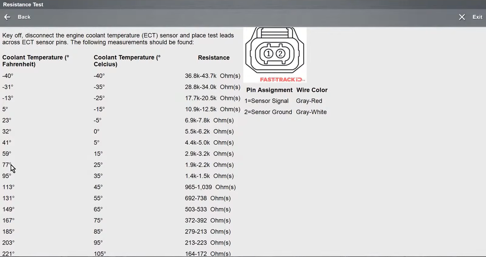
The example shown in the above image demonstrates a Guided Component Test for an Engine Coolant Temperature sensor. The reference chart illustrates a fundamental characteristic of an NTC thermistor: as temperature increases, resistance decreases.
This predictable relationship allows the ECM to accurately determine engine temperature and make informed decisions regarding fuel delivery, ignition timing, cooling fan operation, thermostat control and coolant flow management. Because many thermal management strategies rely on temperature data, accurate temperature monitoring forms the foundation of modern cooling system operation.
Thermostat
Despite advances in cooling system technology, the wax-pellet thermostat remains at the heart of many cooling systems.
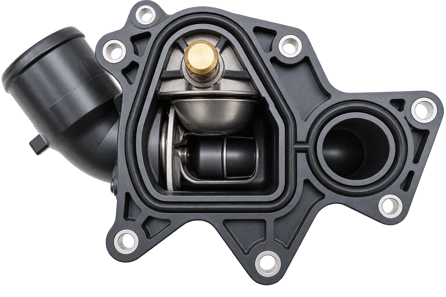
Cross-Section of a Traditional Wax-Pellet Thermostat Assembly
A traditional thermostat consists of a spring-loaded valve, piston and wax element. As coolant temperature increases, the wax expands, acting upon the piston and opening the thermostat valve. This allows coolant to flow through the radiator, helping regulate engine temperature.
The thermostat plays a critical role during engine warm-up, restricting coolant flow until the engine reaches its intended operating temperature. Maintaining higher operating temperatures during warm-up improves combustion efficiency and reduces emissions.
Although thermostat designs have evolved, many modern systems still rely upon the same wax-expansion principle that has been used in automotive applications for decades.
Electronic Heated Thermostat
To provide greater control over engine temperature, many manufacturers use electronically heated thermostats as part of a mapped cooling system strategy.
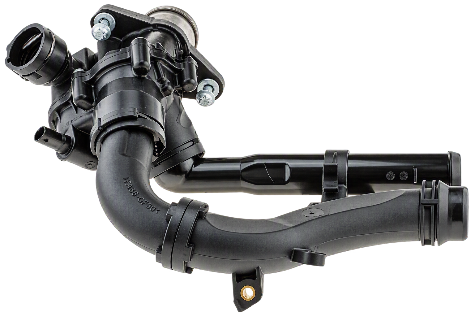
Electronic Heated Thermostat
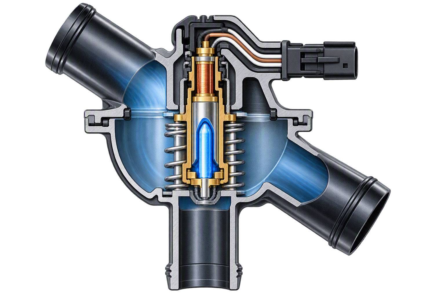
Cross-Section of a Electronic Heated Thermostat
A heated thermostat retains the conventional wax-pellet design but incorporates an electrical heating element. During periods of increased engine load, the ECM can energise the heater, causing the thermostat to open earlier and allowing more coolant to flow through the radiator. This increases cooling capacity when required, while allowing higher operating temperatures during lighter load conditions.
The result is improved thermal management, reduced emissions and better fuel economy compared with a conventional thermostat.
Simplified electronically heated thermostat showing the water inlet (1), electrical connection (2), return spring (3), outlet disc (4) and electrical heating element (5).
Fast-Track® Guided Component Tests provide vehicle-specific information including component operation, pin assignments, connection guidance, known-good values and experience-based troubleshooting tips to support accurate diagnosis.
Electronically Controlled Cooling Fans
Modern cooling fan operation has evolved significantly from simple on/off control. Many modern vehicles use dedicated cooling fan control modules that allow fan speed to be adjusted according to cooling demand. By varying fan speed, the engine management system can maintain more precise operating temperatures, improve efficiency and provide additional cooling when conditions require it.
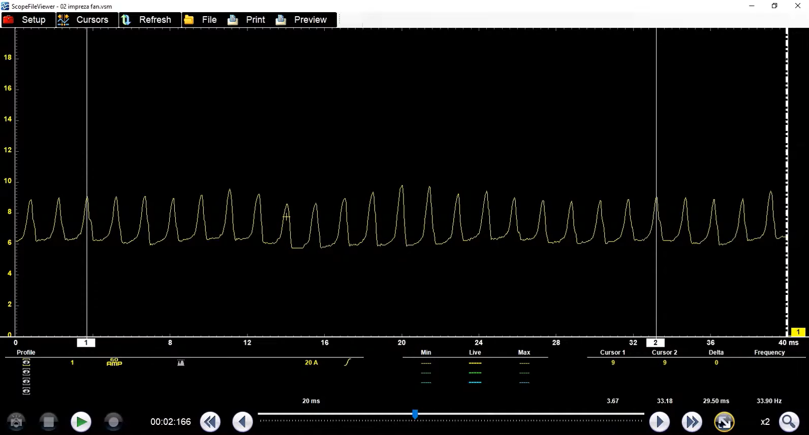
Cooling fan current ramp test captured on a Subaru Impreza
As with many modern cooling system components, cooling fans can be monitored using scan tool data and bi-directional controls. For deeper analysis, technicians can perform a current ramp test using an oscilloscope and current clamp. Because the cooling fan motor is an electric motor, current patterns provide valuable insight into motor condition.
A healthy motor will typically produce evenly spaced current ramps with consistent peak amplitudes. Irregular patterns may indicate internal motor faults or excessive mechanical resistance. Current ramp testing provides a fast, non-intrusive method of evaluating motor condition.
Active Grille Shutters
Another important thermal management technology is the Active Grille Shutter (AGS) system. The active grille shutter uses a grille shutter assembly and actuator to regulate airflow through the radiator and engine compartment.
During cold-start and low-load operating conditions, the shutters can remain partially or fully closed. Restricting airflow helps the engine reach operating temperature more quickly while also reducing aerodynamic drag. As thermal demand increases, the ECM commands the actuator to progressively open the shutters, increasing airflow through the radiator and improving cooling performance.
Many systems perform an automatic calibration routine during engine start-up. During this process, the shutters cycle fully open and closed before moving to their commanded operating position. In addition to improving engine warm-up and cooling performance, active grille shutters contribute to enhanced vehicle aerodynamics and fuel economy.
Electric Water Pumps and Variable Coolant Flow
Electric coolant pumps have become increasingly common throughout the automotive industry. Unlike conventional mechanically driven water pumps, electric pumps can operate independently of engine speed. This allows coolant flow to be controlled according to operating conditions rather than being directly linked to crankshaft speed.
Benefits include faster warm-up, improved fuel economy, reduced emissions, more accurate temperature control and post-shutdown coolant circulation.
Some vehicles also employ variable coolant flow systems that actively regulate circulation rates through different portions of the cooling circuit. By precisely controlling coolant flow, the ECM can maintain optimal operating temperatures across a broader range of conditions while improving overall vehicle efficiency.
Testing Coolant Pumps
Guided component tests allow technicians to command electronically controlled after-run coolant pumps and monitor system response. This helps confirm correct pump operation and quickly identify electrical or control-related faults.
Example of guided testing for an electronically controlled after-run coolant pump.
Auxiliary Cooling Circuits
Modern powertrains frequently utilise multiple cooling circuits to manage different thermal loads.
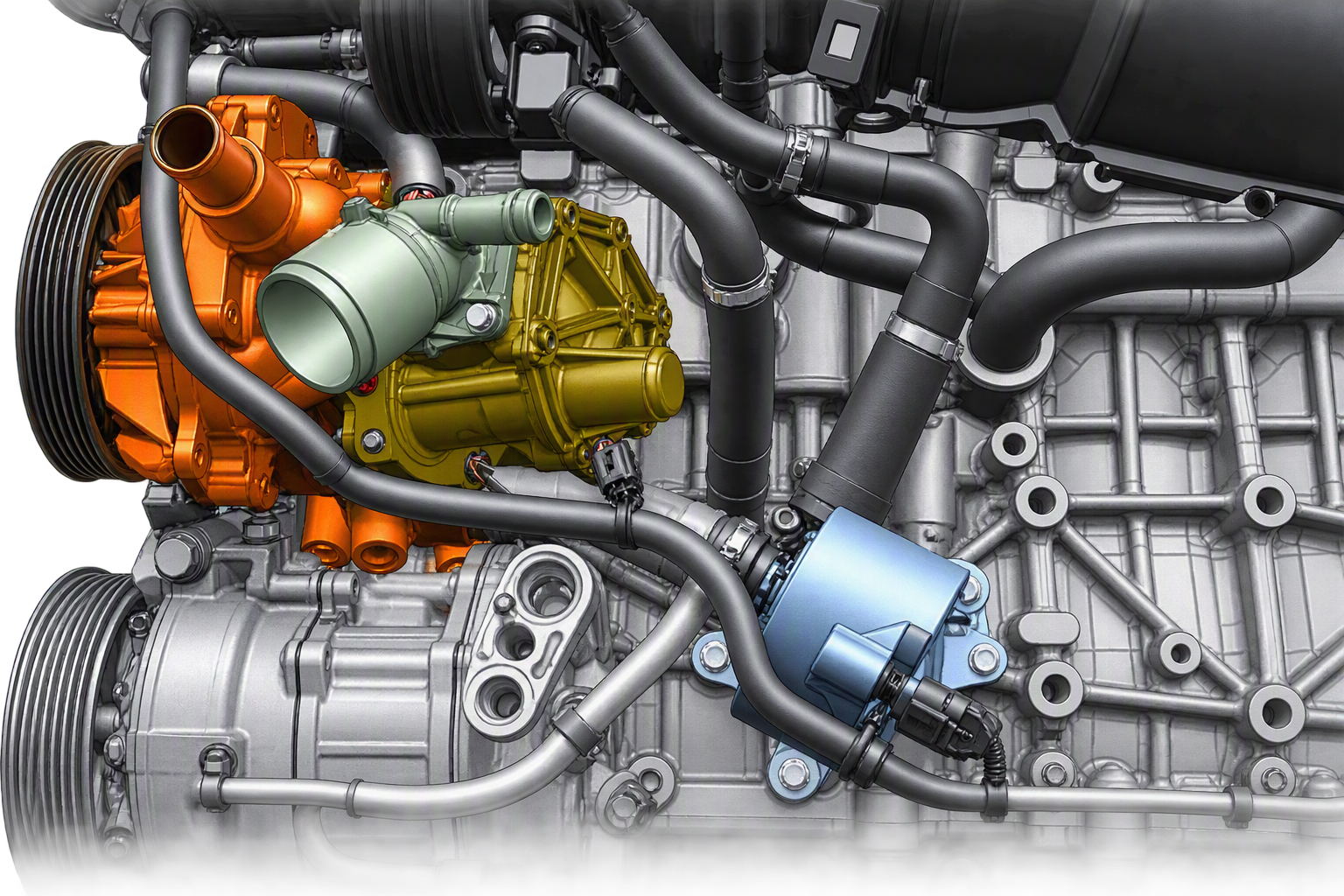
Engine Cooling System Components
The image above highlights the primary water pump, thermostat assembly and an electronically controlled sub water pump used to support a dedicated turbocharger cooling circuit. Separate cooling circuits allow manufacturers to manage component temperatures more precisely and improve overall system efficiency.
This approach is becoming increasingly common as manufacturers seek greater control over component temperatures and vehicle efficiency.
Case Study: 2024 Land Rover® Range Rover Evoque 2.0L I4 Diesel MHEV
A 2024 Range Rover Evoque equipped with a 2.0L I4 Diesel Mild Hybrid powertrain presented with an illuminated Malfunction Indicator Lamp (MIL). Vehicle interrogation identified DTC P26A3: Coolant Pump Variable Flow Actuator Position Sensor Circuit Range/Performance.

The fault relates to the vehicle's variable coolant flow system, where the ECM monitors actuator position feedback to verify that commanded coolant flow matches actual operation. If feedback falls outside expected parameters, a fault code may be stored and the warning lamp illuminated.
Potential causes include actuator or position sensor faults, wiring and connector issues, mechanical restrictions, calibration errors, coolant pump assembly faults, or control module communication issues.
A structured diagnostic process was used to evaluate actuator operation, wiring integrity, power and ground supplies, and overall variable flow system performance. Understanding how the coolant pump interacts with other thermal management components, including the thermostat, cooling fans and active grille shutters, proved essential in identifying the root cause and avoiding unnecessary parts replacement.
Coolant Pump Variable Flow Actuator Position Learn
Following repairs, the manufacturer-specified Coolant Pump Variable Flow Actuator Position Learn procedure was performed. This calibration routine allows the control module to verify actuator operation and position feedback while establishing the parameters required for correct coolant flow control. If this procedure is specified for the vehicle and is not completed, the vehicle may log repeat fault codes or operate incorrectly.
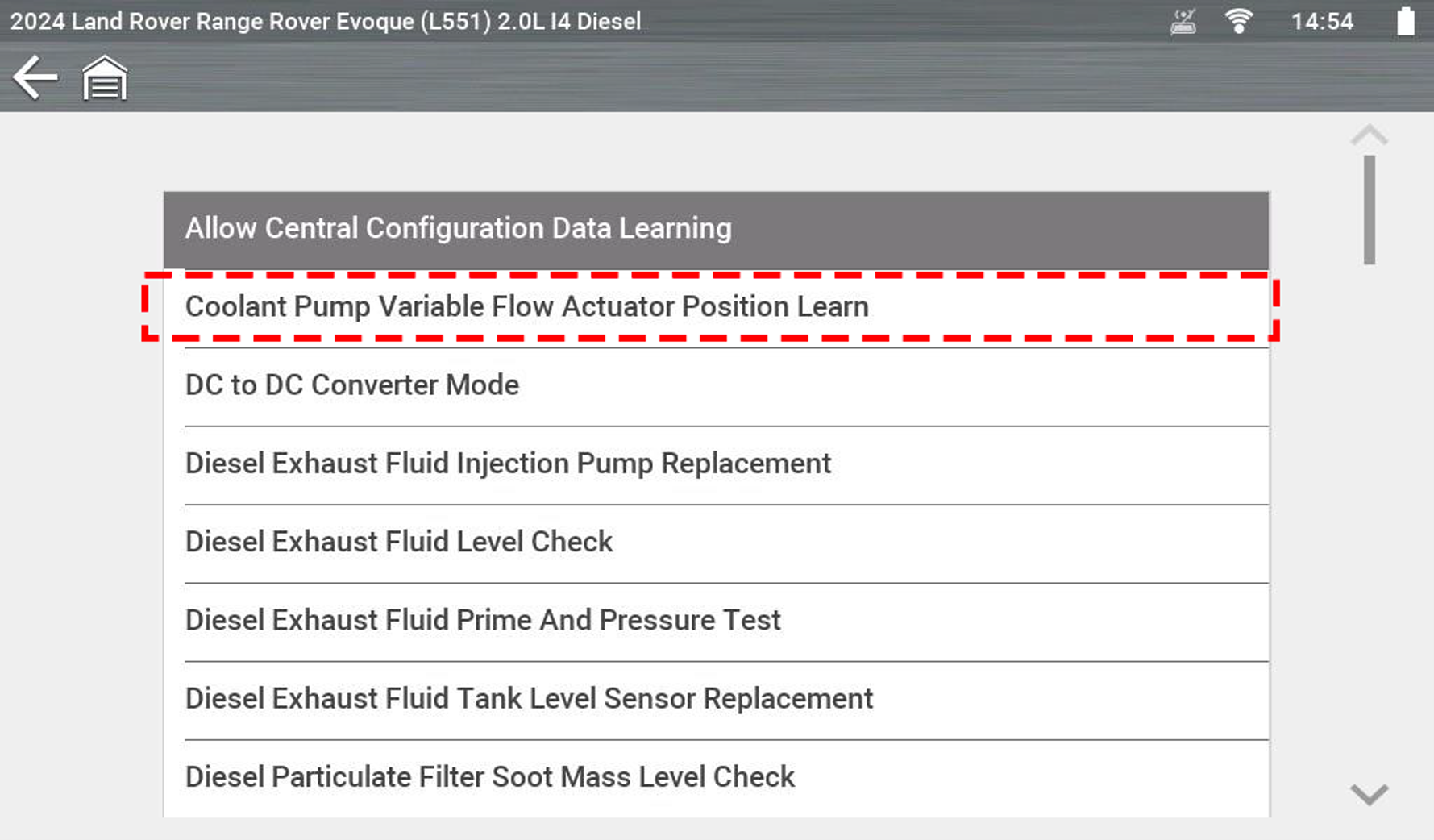
*Shown on a Snap-on® TRITON™
Follow the vehicle manufacturer's current service information and the on-screen instructions. The steps below are an example for the vehicle and software version shown and are not a substitute for the applicable repair information
Operational steps:
- From the main menu select “engine” from the common selections sub-menu
- Select functional tests
- Select special functions
- Select Coolant pump variable Flow Actuator Position Learn
- Set the ignition switch to the ON position (Position 2) and select continue
Ensure that the battery voltage of the vehicle is kept above 12.5 volts for the duration of this diagnostic session. Connect a battery charger or battery support unit to the vehicle if needed. Then select continue
- This routine will initialise the coolant pump variable flow actuator position learning with retaining first learned values updates. Select continue.
- Follow the onscreen instructions to complete the procedure.
Repair Verification
Following completion of the repair and learn procedure, a post-scan was performed, DTCs were cleared and actuator operation, position feedback and cooling system performance were verified during road testing. Normal operation was restored and the fault did not return.
Understanding Modern Cooling Systems
Modern cooling systems have evolved far beyond the traditional radiator, water pump and thermostat arrangement. Electronically controlled thermostats, electric coolant pumps, active grille shutters and PWM-controlled cooling fans now work together as part of an integrated thermal management strategy designed to improve efficiency, reduce emissions and enhance engine protection. As these systems become increasingly sophisticated, understanding component operation, system interactions and required calibration procedures is essential for accurate diagnosis and successful repair.
Recommended Diagnostic Tool for Coolant Pump Diagnosis and Repair
USAGE
Everyday
EXPERIENCE LEVEL
Advanced
TECHNICIAN ROLE
Diagnostic Specialist, Garage Manager/Owner
ADDITIONAL FEATURES
Access to Technical Service Bulletins (TSBs), Lab Scope, Step-by-Step Guided Tests, Suggested Expert Information from Other Techs, Advanced Graphing Features, Known Good Waveforms, Filtered Data, In-Tool Learning
I'm Interested
FAQ’s
1) What is a Coolant Pump Variable Flow Actuator Position Learn procedure?
A manufacturer-specified calibration routine that allows the control module to learn actuator positions and verify feedback following coolant pump replacement or repair.
2) When should a Coolant Pump Variable Flow Actuator Position Learn procedure be performed?
The procedure should be performed following coolant pump replacement where specified by the vehicle manufacturer or applicable service information. It may also be required after other work on the cooling system, depending on the vehicle.
3) Why is the coolant pump relearn important?
If a relearn is required for the vehicle and is not completed, the cooling system may not operate correctly and the vehicle may overheat.
4) Can a vehicle overheat if the relearn procedure is skipped?
Potentially, if a relearn is required for that vehicle and is skipped. The cooling system may not operate correctly following repair, which could contribute to overheating or repeat faults.
5) What is an electronic coolant pump?
An electronic coolant pump is controlled by the engine management system rather than engine speed, allowing more precise coolant flow and temperature control.
6) What is a variable coolant flow system?
A system that actively adjusts coolant circulation according to operating conditions to improve thermal management, fuel economy and emissions performance.
7) What causes DTC P26A3?
Possible causes include actuator faults, position sensor faults, wiring issues, calibration errors, mechanical restrictions or coolant pump assembly faults.
8) How can Snap-on® diagnostic tools help identify coolant pump faults?
Subject to applicable vehicle coverage and software version, supported Snap-on® platforms provide access to live data, functional tests, Guided Component Tests, Complete Code Scan, Diagnostic Health Scan and Fast-Track® Intelligent Diagnostics to help technicians evaluate coolant pump operation and related faults.
9) What coolant pump live data and functional tests are available through Snap-on® diagnostic platforms?
Depending on vehicle coverage, technicians can access coolant pump live data, coolant temperature sensor data, cooling fan information and manufacturer-specific functional tests to verify cooling system operation.
10) Can Snap-on® diagnostic tools perform the Range Rover Evoque Coolant Pump Variable Flow Actuator Position Learn procedure?
Yes, on supported vehicle and software coverage. Supported Snap-on® diagnostic platforms provide access to the Range Rover Evoque Coolant Pump Variable Flow Actuator Position Learn procedure on the 2024 Range Rover Evoque 2.0L I4 Diesel MHEV, allowing technicians to perform the required post-repair coolant pump calibration and initialise the system correctly following replacement.
*This article is intended for informational purposes only and is designed to provide general technical insight. It is not intended to serve as step-by-step repair, service or diagnostic instruction. Always follow manufacturer-approved procedures and safety guidelines when carrying out vehicle diagnostics, cooling system service or repairs.
Technicians should always consult the relevant vehicle manufacturer's service information when carrying out diagnosis, maintenance, servicing or repairs.
Land Rover® and Range Rover® are trademarks of Jaguar Land Rover Limited. Subaru® is a trademark of Subaru Corporation. Any reference to vehicle manufacturers, models or trademarks is for identification and compatibility purposes only and does not imply any affiliation with or endorsement by the respective trademark owners.
Snap-on® diagnostic coverage and functionality may vary by vehicle, model year, software version and platform. Coolant Pump Variable Flow Actuator Position Learn coverage for the 2024 Land Rover® Range Rover Evoque 2.0L I4 Diesel MHEV requires software version 26.4 or higher.